Download
1 / 36
370 likes | 391 Views
Explore the project performance goals, physics requirements, and R&D status of SLAC's Injector project. Learn about the operating range, tolerances, and safety factors, and delve into simulations and sensitivity studies. Discover the impact of mis-positioning, laser pulse requirements, and diagnostics performance. Gain insights into simulations results, tolerances, laser pulse requirements, and spectrometer measurements. Stay informed on the innovative developments and rigorous standards of the SLAC Injector project.

E N D
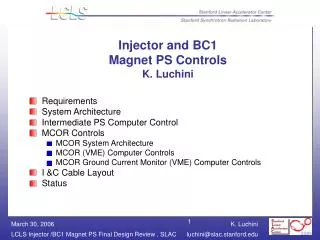
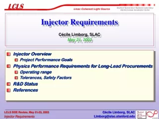
Injector RequirementsCécile Limborg, SLACMay 21, 2003 • Injector Overview • Project Performance Goals • Physics Performance Requirements for Long-Lead Procurements • Operating range • Tolerances, Safety Factors • R&D Status • References Cécile Limborg, SLAC
Preinjector: Cécile Limborg, SLAC
L I N A C H O U S I N G S I D E W A L L e t e r o l e w / 3 0 d e g p r o t a t i o n s M A G N E T I C e c t r o m S p S C 2 X - Y C o r r e c t o r 1 M P E E B 1 V D 0 L E O A N H V U T G 1 A F S C 1 0 ' H I G H R E 1 V M S L 2 C A 1 Y V C - X F 1 1 C 2 0 S ' C L F A I C N C L o w - E D u m p E A L E C R A H T O O L I N A C H O U S I N G S I D E W A L L R U 1 3 ' - 3 . 2 7 " S I N L G I N S I A D C 3 E C E 2 V S M C L W A P 2 V 1 O B M A R C T H L O 3 L E 1 M E 0 P R V ' 4 B L A C E A C S V C N E T L E L R I A T G 7 7 ' ' H H I I G G H H O H R T S O 5 U M P 6 R C B S C 5 E C 3 S M M 4 M C 2 O P R B T O 1 D 0 I E F Q 2 I 0 C E 2 Q O A E 6 T M R 7 I P E C B K O S C I N K 3 F R T 3 T R 0 O E O Q L I 4 0 N E 8 1 7 Q A C M 0 1 0 ' H I G H 4 S S P C R W B T O 8 M P B 2 0 S W 5 R T O L I N A C H O U S I N G S I D E W A L L L I N A C H O U S I N G S I D E W A L L 0 1 C 1 S 0 E P E N . 2 1 - 1 3 P E N . 2 0 - 1 6 C 5 0 P E N . 2 0 - 1 5 S 6 M R W 9 C T P E N . 2 0 - 1 7 4 C 9 1 O M 0 S M 1 2 " B C 0 P B M B 3 4 9 . 4 Q 4 2 Q 1 2 0 0 1 8 0 1 0 1 2 2 M M S 1 2 A C C E L R T U B E M M 1 A C C E L 1 0 ' 0 M 3 A C C E L E R A T O R 1 0 ' A C C E L 1 C 1 0 ' W Q Q T C B Q M O P P S O S 9 B B E P R B T O 0 7 1 1 R 3 " 0 M S E C T I O N 2 0 - 8 C T S E C T I O N 2 0 - 8 A M R P S E C T I O N 2 0 - 8 B V A L V E P 1 O I M B S E C T I O N 2 1 - 1 B R E 0 T U B E U T M D 9 0 P B H E A - P E Q M Q M O T R 1 0 E 0 0 0 0 C M 6 O P E P - 2 H E / L E B Y P A S S 2 3 4 1 Q B B P M 1 3 T L E S B E A M D R I F T S E C T I O N A C C E L E R A T O R S E C T I O N S L I N A C H O U S I N G S I D E W A L L L I N A C H O U S I N G S I D E W A L L LCLS Injector Long Lead Items: The Injector Cathode Load Lock RF Photocathode Gun Gun Spectrometer SLAC 3-m Accelerator Sections Transverse RF Cavity (Longitudinal diag.) Drive Laser Upstairs in Sector 20 Alcove Shield Wall Straight Ahead Spectrometer & Diag. Cécile Limborg, SLAC
Injector Overview • Project Performance Goal • projected < 1.2 mm.mrad • slice < 1.0 mm.mrad for 80 slices out of 100 • slice(80%) projected emittance for the core 80 slices for 1nC, 10ps pulse at 150 MeV,in the presence of “jitter” errors at 120Hz repetition rate Cécile Limborg, SLAC
th = 0.72 mm.mrad th = 0.36 mm.mrad Simulations: Thermal emittance, Finite Rise Time • Thermal emittance of 0.72 mm.mrad (see Ref [1]) • Finite rise time of 0.7ps (from 10-90% level) Cécile Limborg, SLAC
Simulations: Operating Range and Sensitivity Cécile Limborg, SLAC
Simulations: Sensitivity Study: Combination of Errors • Using extreme values of parameters deviations meeting regulation specifications 2^6 possibilities = 64 runs Cécile Limborg, SLAC
Results of Simulations: Tolerances (*) combined with uniformity of QE Cécile Limborg, SLAC
First Linac Section Mis-positioning • Effects of Wakefields : • Position : 150 m maximum • Angular : 0.12 mrad • With alignment & steering : those requirements are easily met (BPM resolution 20 m ) At end beamline At end beamline ~2% increase level ~2% increase level Cécile Limborg, SLAC
Requirements on Laser Pulse Cécile Limborg, SLAC
Physics Performance Requirements for Diagnostics • Gun Spectrometer • Energy • Correlated Energy • Uniformity of line density • Emittance measurement • Three screen measurement (with wire scanners) • Straight Ahead Spectrometer • Energy • Energy Spread, Correlated and Uncorrelated • Slice emittance (in combination with deflecting cavity) Cécile Limborg, SLAC
Gun Spectrometer Measurements (see Ref [8]) • Absolute Energy at gun exit • Energy Spread • Correlated for all charges • Uncorrelated at low charge • Resolving Power large (10keV at 5MeV, = 2.10-3) • Uniformity of line density • Point-to-point imaging of beam at first screen ( in both planes) • Relay-imaging system: cathode first screen (XY image) spectrometer screen Cécile Limborg, SLAC
Gun Spectrometer Can Measure Uniformity of Line Charge Density • can resolve a minimum of 5% initial modulation Cécile Limborg, SLAC
x y t E y ~ k1t x ~ k2E Straight Ahead Spectrometer • Absolute Energy Measurements • Correlated and Uncorrelated energy spread • Resolution: 10keV at 150MeV by focusing beam down to 115m • Measurement of slice emittance • Full 6D emittance measurement in combination with Transverse Deflecting cavity • Details of parameters in Ref [8], 35 bending magnet, standard SLAC Quadrupoles Transverse Deflecting cavity (Ref [7]) Longitudinal emittance Spectrometer Uncorrelated energy spread 2 in A xo2+ B yo2 +,uncor2 xo,yo small at waist (object plane imaged) Slice emittance Cécile Limborg, SLAC
head tail 150 100 50 Time (ps) 0 -1.5 -1 -0.5 0 0.5 1 2 1 0 5 10 R&D Status: GTF Measurements • GTF measurements (Ref [10]) 300pC slice = 1.5 mm.mrad for 130 A ~ close to LCLS requirements Similar measurements at the DUVFEL facility (Spring 2002) Spectrometer Image of Slice Quad Scan Data Peak Current (A) Instantaneous Peak Current n (mm mrad) Slice Emittances longitudinal emittance Slice number Cécile Limborg, SLAC
DUVFEL Measurements • PARMELA Simulations of DUVFEL measurements (Ref.[1]) • Simulations match measurements very well • For slice emittance and Twiss parameters • For various solenoid fields After including thermal emittance, gun field balance between the two cells, transverse non-uniformity and longitudinal profile • Thermal emittance experiment • Confirms the 0.6 mm.mrad per mm radius of laser spot size Cécile Limborg, SLAC
Solenoid = 104 A Solenoid = 98 A • DUVFEL measurements (see Ref [1]) • 200 pC • Good Agreement Slice Emittance and Twiss Parameters for the various solenoid fields Cécile Limborg, SLAC
R&D Status • Other Simulation work • Comparison of codes [6] (5 codes: TREDI, BEAMPATH, HOMDYN, ASTRA, PARMELA) for the LCLS PhotoInjector • Confirms small uncorrelated energy spread • Confirms adequacy of LCLS present tuning • Simulations of GTF longitudinal emittance measurements [9] • Good agreement on measured energy spread • Comparison with PIC codes for [5] • Good approximation of dynamics in PARMELA at extraction • Wakefield included in PARMELA • Benchmarked with Elegant Cécile Limborg, SLAC
CONCLUSIONS • Most of the LCLS injector linac is standard SLAC design, no technical risk • Gun performance has received a lot of attention; simulations agree with measurements (for both GTF and DUVFEL) • LCLS has safety margin for reaching saturation with this injector Cécile Limborg, SLAC
LIST OF REFERNCES • Simulations vs Experiments • [1] “PARMELA vs Measurements for GTF and DUVFEL “, EPAC 2002, (SLAC-PUB-9556) • [2] “Comparison of PARMELA Simulations with Longitudinal Emittance Measurements at the SLAC Gun Test Facility” , PAC03 • [3] “Simulations of the quadrupole scan measurement technique” [ICFA Wokshop, to be published as a SLAC note] • Simulations • [5] “Simulations Issues for PhotoInjectors” , ICAPS02 • [6] “Code Comparison for Simulations of Photo-injectors”, PAC03 Cécile Limborg, SLAC
LIST OF REFERNCES • Instrumentation • [7] “Transverse Deflecting Cavity” R.Akre, et al. ,WPAH116.PDF , PAC 01, Chicago 2001 • [8] “Spectrometers for the LCLS PhotoInjector Beamline”, C.Limborg, LCLS Tech Note • Experiment & PARMELA vs Experiment • [9] “Comparison of PARMELA Simulations with Longitudinal Emittance Measurements at the SLAC Gun Test Facility”,C.Limborg, PAC 03 • [10] “Slice Emittance Measurements At the SLAC Gun Test Facility ” D.Dowell, FEL02, ANL,Chicago,August 02, (SLAC-PUB-9540) Cécile Limborg, SLAC
BACK- UP SLIDES Cécile Limborg, SLAC
Physics Performance Requirements Solenoid 1 0.3% gun2.5 Egun0.5% Linac Field 12 % (EFinal = 150 MeV ) Solenoid 2 20% Cécile Limborg, SLAC
Simulations: Sensitivity Study • 64 runs with maximum sensitivity errors 2^6 = 64 runs Cécile Limborg, SLAC
Charge 5% Radius 5% Physics Performance Requirements • Charge • 7 % ok , objective 5% • Laser Spot Size • 1% very easy to maintain Cécile Limborg, SLAC
5% level Physics Performance Requirements • Laser Quality • Longitudinal Flat top Flatness • Emittance deterioration • Result : • For > 240 m, Modulation < 20% • For 240 m < , Modulation < 30% 20% peak-to-peak Cécile Limborg, SLAC
Physics Performance Requirements • Laser Quality • Longitudinal Flat Top Flatness • Source of CSR in BC2 if modulation in range 100m < <200 m • Result: favorable situation since good dilution for short wavelengths ( < 240 m ) Cécile Limborg, SLAC
Physics Performance Requirements • Laser Quality: Transverse Uniformity • High frequency modulations get diluted [1], low frequency is the most damaging • Slope across Spot • Offset of center of gravity transverse wakefield in linac • Criteria: deterioration of slice emittance at linac entrance by less than 5% or center of gravity off by less than 100 m at linac entrance • Result : No more than +/- 15% (+/- 10% feasible and will be the tolerance) Cécile Limborg, SLAC
Physics Performance Requirements • Laser Quality: Transverse Uniformity • “Checker board” type : low frequency is worst case [1] • Generates ellipticity but no centroid offset • Generates slice emittance growth • Result : maximum +/ 15% modulation (again 10% feasible and is the specification) Cécile Limborg, SLAC
Physics Performance Requirements • Alignment Linac Section : • Head-to-Tail Offset at entrance Linac • Result : +/- 50 m Cécile Limborg, SLAC
Physics Performance Requirements • Alignment : Solenoid Tilt • Creates centroid offset and angle (but can be corrected by steering) • Creates slice emittance increase • Criteria : • slice(80%) at entrance Linac does not increase emittance by more than 1% • Head-tail centroid offset less than 100 m at entrance linac • Result : 1.5 mrad maximum • No problem with offset of centroids, no problem in angle either Cécile Limborg, SLAC
Physics Performance Requirements • Alignment : Solenoid Offset • Creates offset and angle of bunch (can be corrected by steering) • Creates head-tail centroid offsets and angle • Criteria : • slice(80%) at entrance Linac not increase by more than 1% • Head-tail centroid offset less than 100 m • Result : 500 m maximum Cécile Limborg, SLAC
Physics Performance Requirements • Alignment : Laser Position Steering • Creates offset and angle of bunch • Creates head-tail centroids offsets and angles • Creates slice emittance growth • Criteria: • slice(80%) at entrance Linac not increase by more than 5% • Head-tail centroid offset less than 100 m • Result : 100 m Cécile Limborg, SLAC
Physics Performance Requirements • Alignment : Laser Position Steering Cécile Limborg, SLAC
Solenoid = 98 A Data Parmela DUVFEL EXPERIMENT Good match of Slice Emittance and Twiss Parameters Parameters: 200 pC Solenoid = 104 A Solenoid = 108 A Cécile Limborg, SLAC
Spectrometer 2 Design • Preliminary Design • The dipole magnet was chosen to give 35 bending angle • We do a point-to-point imaging of the waist, the energy is 150 MeV • uses standard quadrupoles • 2.5 m long • space available for installing sextupoles • Resolution of 10keV at 150MeV, = 6.6.10-5 ,Resolving power too small • <x2> =~ R112 <xo2> + R162 < 2> • Beam size at waist for having xo small , xo = 115 m Cécile Limborg, SLAC