Download
1 / 25
250 likes | 357 Views
Learn about Ethernet addressing, LAN transmission methods, broadcast domains, VLAN operation, and more for efficient network management and connectivity.

E N D
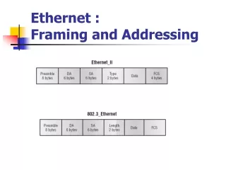
802.2 802.2 frame • 802.3 Ethernet frame cannot by itself identify the upper-layer (Network) protocol • The IEEE defined the 802.2 LLC (Logical Link Control) specifications to provide this function and more. • An 802.2 frame is an 802.3 frame with the LLC information in the data field of the header so we know what the upper-layer protocol is.
SNAP SNAP (SubNetwork Access Protocol) frame • The SNAP frame has its own protocol field to identify the upper-layer protocol • This is really a way to allow an Ethernet_II Ether-Type field to be used in an 802.3 frame • SNAP frame can be identified easily because the DSAP and SSAP fields are always AA, and the Command field is always 3.
Types of Ethernet Addresses • Ethernet addresses, also frequently called MAC addresses, are 6 bytes in length, typically listed in hexadecimal form • There are three main types of Ethernet address
LAN Transmission Methods Unicast Process • Unicast Process • The source addresses the packet with the destination address • The packet is sent into the network • The destination receives the packet
LAN Transmission MethodsMulticast Process • Multicast Process • The source addresses the packet using a multicast address • The packet is sent into the network • A copy is delivered to each destination that is included in the multicast address
LAN Transmission MethodsBroadcast Process • Broadcast Process • The source addresses the packet with the broadcast address • The packet is sent into the network • The packet copies are delivered to all destinations
Ethernet Address Formats • The IEEE intends for unicast addresses to be unique in the universe by administering the assignment of MAC addresses • The IEEE assigns each vendor a code to use as the first 3 bytes of its MAC addresses; that first half of the addresses is called the Organizationally Unique Identifier (OUI) • The IEEE expects each manufacturer to use its OUI for the first 3 bytes of the MAC assigned to any Ethernet product created by that vendor • The vendor then assigns a unique value in the low-order 3 bytes for each Ethernet card that it manufactures—thereby ensuring global uniqueness of MAC addresses
Ethernet Address Formats I/G = individual/Group bit U/L = Universal/Local bit
Broadcast Domains • In an Ethernet LAN, a set of devices that receive a broadcast sent by any one of the devices in the same set is called a broadcast domain • A switch simply forwards all broadcasts out all interfaces, except the interface on which it received the frame • As a result, all the interfaces on an individual switch are in the same broadcast domain • Also, if the switch connects to other switches and hubs, the interfaces on those switches and hubs are also in the same broadcast domain
Switch Operation • There are three primary operating modes used to handle frame switching: • Cut-through • Store-and-forward • Fragment Free (modified cut-through)
Virtual LAN (VLAN) • A VLAN is simply an administratively defined subset of switch ports that are in the same broadcast domain • Ports can be grouped into different VLANs on a single switch, and on multiple interconnected switches as well • By creating multiple VLANs, the switches create multiple broadcast domains • By doing so, a broadcast sent by a device in one VLAN is forwarded to the other devices in that same VLAN; however, the broadcast is not forwarded to devices in the other VLANs • Layer 2 switches forward frames between devices in the same VLAN, but they do not forward frames between two devices in different VLANs
VLAN Trunking ISL encapsulation IEEE 802.1Q tagged frame