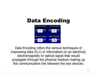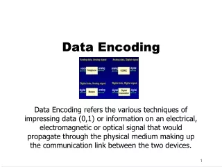
Line Encoding
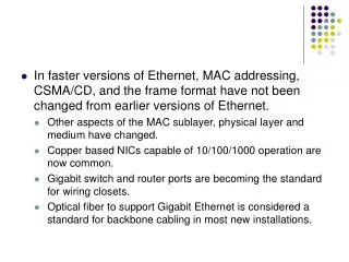
In faster versions of Ethernet, MAC addressing, CSMA/CD, and the frame format have not been changed from earlier versions of Ethernet. Other aspects of the MAC sublayer, physical layer and medium have changed. Copper based NICs capable of 10/100/1000 operation are now common.

Line Encoding
E N D
Presentation Transcript
In faster versions of Ethernet, MAC addressing, CSMA/CD, and the frame format have not been changed from earlier versions of Ethernet. • Other aspects of the MAC sublayer, physical layer and medium have changed. • Copper based NICs capable of 10/100/1000 operation are now common. • Gigabit switch and router ports are becoming the standard for wiring closets. • Optical fiber to support Gigabit Ethernet is considered a standard for backbone cabling in most new installations.
10BASE5, 10BASE2, and 10BASE-T Ethernet are considered Legacy Ethernet. The four common features of Legacy Ethernet are timing parameters, frame format, transmission process, and a basic design rule. • 10BASE5, 10BASE2, and 10BASE-T all share the same timing parameters • 10BASE5, 10BASE2, and 10BASE-T also have a common frame format
Line Encoding • All 10 Mbps forms of Ethernet take octets received from the MAC sublayer and perform a process called line encoding. Line encoding describes how the bits are actually signaled on the wire. • The form of encoding used in 10 Mbps systems is called “Manchester.” • Manchester encoding relies on the direction of the edge transition in the middle of the timing window to determine the binary value for that bit period. • the binary bit values are indicated by the direction of change during any given bit period. The waveform voltage levels at the beginning or end of any bit period are not factors when determining binary values.
Timing Limits • The timing limits are based on parameters such as: • Cable length and its propagation delay • Delay of repeaters • Delay of transceivers • Interframe gap shrinkage • Delays within the station
10BASE5 One possible configuration for a maximum end-to-end collision domain. Between any two distant stations only three repeated segments are permitted to have stations connected to them, with the other two repeated segments used only as link segments to extend the network.
10BASE2 (Cont’d) • 10BASE2 also uses Manchester encoding • 10BASE2 has a stranded central conductor. Each of the maximum five segments of thin coax may be up to 185 meters long and each station is connected directly to the BNC “T” connector on the coax. • Only one station can transmit at a time or else a collision will occur. 10BASE2 also uses half-duplex. The maximum transmission rate of 10BASE2 is 10 Mbps. • There may be up to 30 stations on any individual 10BASE2 segment. Out of the five consecutive segments in series between any two distant stations, only three may have stations attached.
10BASET (Cont’d) • 10BASE-T also uses Manchester encoding. • 10BASE-T UTP cable has a solid conductor for each wire in the maximum 90 meter horizontal cable. • UTP cable uses eight-pin RJ-45 connectors. • Though Category 3 cable is adequate for use on 10BASE-T networks, it is strongly recommended that any new cable installations be made with Category 5e or better. • All four pairs of wires should be used either with the T568-A or T568-B cable pinout arrangement. • 10BASE-T carries 10 Mbps of traffic in half-duplex mode and 20 Mbps in full-duplex mode
100BASE-TX • 100-Mbps Ethernet is also known as Fast Ethernet • 100BASE-TX, which is a copper UTP medium • 100BASE-FX, which is a multimode optical fiber medium.
100BASE-TX (Cont’d) • Three characteristics common to 100BASE-TX and 100BASE-FX • Timing parameters • Frame format, • Parts of the transmission process. • 100BASE-TX and 100-BASE-FX both share timing parameters. Note that one bit time in 100-Mbps Ethernet is 10nsec = .01 microseconds = 1 100-millionth of a second.
100BASE-TX (Cont’d) • Fast Ethernet represents a 10-fold increase in speed over 10BASE-T. • Because of the increase in speed, extra care must be taken because the bits being sent are getting shorter in duration and occurring more frequently. • These higher frequency signals are more susceptible to noise. • Two separate encoding steps are used by 100-Mbps Ethernet. • The first part of the encoding uses a technique called 4B/5B, • second part of the encoding is the actual line encoding specific to copper or fiber.
100BASE-FX MLT3 Encoding • 100BASE-TX uses 4B/5B encoding, which is then scrambled and converted to multi-level transmit-3 levels or MLT-3. • No transition indicates that a binary 0 is present. • A transition in the center of the timing window. A binary 1 is represented by a transition. • Rising or falling edges indicate 1s. Very steep signal changes indicate 1s. Any noticeable horizontal line in the signal indicates a 0. • 100BASE-TX carries 100 Mbps of traffic in half-duplex mode. In full-duplex mode, 100BASE-TX can exchange 200 Mbps of traffic.
100BASE-FX (Cont’d) • The timing, frame format, and transmission are all common to both versions of 100 Mbps Fast Ethernet. 100BASE-FX also uses 4B/5B encoding • A binary 1 is represented by a transition • No transition indicates a binary 0 • Fiber pair with either ST or SC connectors is most commonly used. • 200 Mbps transmission is possible because of the separate Transmit and Receive paths in 100BASE-FX optical fiber. NRZI Encoding
Fast Ethernet architecture • A Class I repeater may introduce up to 140 bit-times of latency. • Any repeater that changes between one Ethernet implementation and another is a Class I repeater. • A Class II repeater may only introduce a maximum of 92 bit-times latency. • Because of the reduced latency it is possible to have two Class II repeaters in series, but only if the cable between them is very short. • May not exceed 5 meters
Gigabit Ethernet • The 1000-Mbps Ethernet or Gigabit Ethernet standards represent transmission using both fiber and copper media • They use a 1 nanosecond (0.000000001 seconds) or 1 billionth of a second bit time • The Gigabit Ethernet frame has the same format as is used for 10 and 100-Mbps Ethernet. Depending on the implementation, Gigabit Ethernet may use different processes to convert frames to bits on the cable
Gigabit Ethernet (Cont’d) • Due to the increased speeds of newer standards, the shorter duration bit times require special considerations. • Since the bits are introduced on the medium for a shorter duration and more often, timing is critical. • High-speed transmission requires frequencies closer to copper medium bandwidth limitations. This causes the bits to be more susceptible to noise on copper media
Gigabit Ethernet (Cont’d) • Gigabit Ethernet to use two separate encoding steps. Data transmission is made more efficient by using codes to represent the binary bit stream. The encoded data provides synchronization, efficient usage of bandwidth, and improved Signal-to-Noise Ratio characteristics • At the physical layer, the bit patterns from the MAC layer are converted into symbols. • The symbols may also be control information such as start frame, end frame, medium idle conditions. The frame is coded into control symbols and data symbols to increase in network throughput.
Gigabit Ethernet (Cont’d) • Fiber-based Gigabit Ethernet (1000BASE-X) uses 8B/10B encoding which is similar to the 4B/5B concept. • This is followed by the simple Non-Return to Zero (NRZ) line encoding of light on optical fiber. This simpler encoding process is possible because the fiber medium can carry higher bandwidth signals
Gigabit Ethernet (Cont’d) • Cat 5e cable can reliably carry up to 125 Mbps of traffic • Getting 1000 Mbps (Gigabit) of bandwidth. • The first step is to use all four pairs of wires instead of the traditional two pairs of wires. • This is done using complex circuitry to allow full duplex transmissions on the same wire pair. This provides 250 Mbps per pair. • Four-wire pairs provide 1000 Mbps. • Since the information travels simultaneously across the four paths, the circuitry has to divide frames at the transmitter and reassemble them at the receiver.
Gigabit Ethernet (Cont’d) • The 1000BASE-T encoding with 4D-PAM5 line encoding is used on Cat 5e or better UTP • Transmission and reception of data happens in both directions on the same wire at the same time • This results in a permanent collision on the wire pairs. • These collisions result in complex voltage patterns. With the complex integrated circuits using techniques such as echo cancellation, Layer 1 Forward Error Correction (FEC), and prudent selection of voltage levels, the system achieves the 1Gigabit throughput.
Gigabit Ethernet (Cont’d) • 9 voltage levels found on the cable in idle periods • During data transmission periods there are 17 voltage levels found on the cable. • With this large number of states and the effects of noise, the signal on the wire looks more analog than digital. • noise due to cable and termination problems. • Data from the sending station is divided into four parallel streams, encoded, transmitted and detected in parallel, and then reassembled into one received bit stream
1000BASE-SX and LX • The IEEE 802.3 standard recommends that Gigabit Ethernet over fiber be the preferred backbone technology • The timing, frame format, and transmission are common to all versions of 1000 Mbps. • Two signal-encoding schemes are defined at the physical layer. • The 8B/ 10B scheme is used for optical fiber and shielded copper media • Pulse amplitude modulation 5 (PAM5) is used for UTP.
1000BASE-SX and LX • 1000BASE-X uses 8B/10B encoding converted to non-return to zero (NRZ) line encoding • NRZ encoding relies on the signal level found in the timing window to determine the binary value for that bit period • the determination of whether a bit is a zero or a one is made by the level of the signal rather than when the signal changes levels
1000BASE-SX and LX • The Media Access Control method treats the link as point-to-point. • Since separate fibers are used for transmitting (Tx) and receiving (Rx) the connection is inherently full duplex. • Gigabit Ethernet permits only a single repeater between two stations
Gigabit Ethernet architecture • The distance limitations of full-duplex links are only limited by the medium, and not the round-trip delay • Daisy-chaining, star, and extended star topologies are all allowed. The issue then becomes one of logical topology and data flow, not timing or distance limitations. • Modification of the architecture rules is strongly discouraged for 1000BASE-T. • At 100 meters, 1000BASE-T is operating close to the edge of the ability of the hardware to recover the transmitted signal. • Any cabling problems or environmental noise could render an otherwise compliant cable inoperable even at distances that are within the specification.
Gigabit Ethernet architecture 1000BASE SX 1000BASE LX
10-Gigabit Ethernet • 10-Gigabit Ethernet (10GbE) is evolving for not only LANs, but also MANs, and WANs. • Frame format is the same, allowing interoperability between all varieties of legacy, fast, gigabit, and 10 Gigabit, with no reframing or protocol conversions. • Bit time is now 0.1 nanoseconds. All other time variables scale accordingly. • Since only full-duplex fiber connections are used, CSMA/CD is not necessary • The IEEE 802.3 sublayers within OSI Layers 1 and 2 are mostly preserved, with a few additions to accommodate 40 km fiber links and interoperability with SONET/SDH technologies. • Flexible, efficient, reliable, relatively low cost end-to-end Ethernet networks become possible. • TCP/IP can run over LANs, MANs, and WANs with one Layer 2 Transport method.
10-Gigabit Ethernet architectures • For 10 GbE transmissions, each data bit duration is 0.1 nanosecond. • 1,000 GbE data bits / one data bit in a 10-Mbps Ethernet data stream. • Because of the short duration of the 10 GbE data bit, it is often difficult to separate a data bit from noise. • 10 GbE data transmissions rely on exact bit timing to separate the data from the effects of noise on the physical layer. This is the purpose of synchronization.
10-Gigabit Ethernet uses two separate encoding steps. By using codes to represent the user data, transmission is made more efficient. The encoded data provides synchronization, efficient usage of bandwidth, and improved Signal-to-Noise Ratio characteristics • Signals broken into 4 separate streams • 4 laser sources used to provide optical signal • Optical signal is sent through multiplexer • Multiplexed signal sent onto fiber medium
Future of Ethernet • The future of networking media is three-fold: • Copper (up to 1000 Mbps, perhaps more) • Wireless (approaching 100 Mbps, perhaps more) • Optical fiber (currently at 10,000 Mbps and soon to be more) • Copper and wireless media have certain physical and practical limitations on the highest frequency signals that can be transmitted. • Not a limiting factor for optical fiber in the foreseeable future. • The bandwidth limitations on optical fiber are extremely large and are not yet being threatened. In fiber systems, it is the electronics technology (such as emitters and detectors) and fiber manufacturing processes that most limit the speed.