Chapter 14 Resonance Circuits
200 likes | 432 Views
Chapter 14 Resonance Circuits. Chapter Objectives: Understand the Concept of Transfer Functions. Be Familiar with the Decibel Scale. Learn how to make Bode Magnitude and Phase plots. Learn about series and parallel resonant RLC circuits .

Chapter 14 Resonance Circuits
E N D
Presentation Transcript
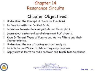
Chapter 14Resonance Circuits Chapter Objectives: • Understand the Concept of Transfer Functions. • Be Familiar with the Decibel Scale. • Learn how to make Bode Magnitude and Phase plots. • Learn about series and parallel resonant RLC circuits. • Know Different Types of Passive and Active Filters and their Characteristics. • Understand the use of scaling in circuit analysis. • Be Able to use PSpice to obtain frequency response. • Apply what is learnt to radio receiver and touch-tone telephone. Huseyin Bilgekul Eeng 224 Circuit Theory II Department of Electrical and Electronic Engineering Eastern Mediterranean University
SERIES RESONANCE • Resonanceis a condition in an RLC circuit in which the capacitive and inductive reactance are equal in magnitude, thereby resulting in purely resistive impedance. • The features of series resonance: • The impedance is purely resistive, Z = R; • The supply voltage Vs and the current I are in phase (cosq = 1) • The magnitude of the transfer function H(ω) = Z(ω) is minimum; • The inductor voltage and capacitor voltage can be much more than the source voltage.
SERIES RESONANCE VR, VL, VC, and I versus frequency for a series resonant circuit.
SERIES RESONANCE Inductive reactance versus frequency. Capacitive reactance versus frequency. ZT(total impedance) versus frequency for the series resonant circuit. Placing the frequency response of the inductive and capacitive reactance of a series R-L-C circuit on the same set of axes.
PHASE OF SERIES RESONANCE CIRCUIT fo Phase plot for the series resonant circuit.
SERIES RESONANCE • Resonance occurs when the circuit has a complex conjugate pair of poles. • Resonance allows frequency discrimination in circuits. • Resonance occurs in a circuit that has at least one inductor and one capacitor. At Resonance: 1)Impedance is purely resistive. 2) The voltage and current are in phase. 3) The transfer function H()= Z() is Minimum 4) Inductor and capacitor voltages can be much more than (Q times) source voltage.
BANDWIDTH of SERIES RESONANCE • Current versus frequency for the series resonant circuit. Half Power Frequencies Dissipated power is half of the maximum value. • The half-power frequencies 1 and 2 can be obtained by setting,
The frequencies corresponding to 0.707 of the maximum current are called the band frequencies, cutoff frequencies, or half-power frequencies (ƒ1, ƒ2). Half-power frequencies are those frequencies at which the power delivered is one-half that delivered at resonant frequency. The range of frequencies between the two are referred to as bandwidth (abbreviated BW) of the resonant circuit. Since the resonant circuit is adjusted to select a band of frequencies it is called a selectivity curve. The shape of the curve depends on each element of the series R-L-C circuit. If resistance is made smaller with a fixed inductance and capacitance, the bandwidth decreases and the selectivity increases. If the ratio L/C increases with fixed resistance, the bandwidth again decreases with an increase in selectivity. Selectivity
BANDWIDTH OF SERIES RESONANCE • The width of the response is measured by the BANDWIDTH. • BANDWIDTHis the difference between the half-power frequencies. • Resonance frequency can be obtained from the half-power frequencies. • The SHARPNESS of the resonance is measured by the QUALITY FACTOR. • QUALITY FACTOR is the ratio of the resonance frequency to the bandwidth. The higher the Q the smaller is the bandwidth.
Effect on Selectivity of R, L, C forSeries Resonance Effect of R on selectivity Effect of L and C on selectivity
PARALLEL RESONANCE • Resonance is a condition in an RLC circuit in which the capacitive and inductive reactances are equal in magnitude, resulting in a purely resistive impedance. • Parallel resonance circuit behaves similarly but in opposite fashion compared to series resonant circuit. • The admitance is minimum at resonance or impedance is maximum. Parallel resonant circuit.
PARALLEL RESONANCE • At Resonance frequency: • 1) Admitance is purely resistive. • 2) The voltage and current are in phase. • 3) The transfer function H()= Y() is Minimum. • 4) Inductor and capacitor currents can be much more than the source current.
PARALLEL RESONANCE Voltage versus frequency for the parallel resonant circuit. • The half-power frequencies can be obtained as:
Dual-channel 15-band “Constant Q” Graphic Equalizer The equalizer changes the contribution of the different frequency components of the music signal according to the listeners’s wish. Gains given to different frequency components of the music signal.