Download
1 / 26
570 likes | 1.63k Views
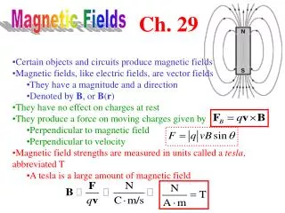
Magnetic Circuits and Transformers. Magnetic Fields Magnetic Circuits Inductance and Mutual Inductance Magnetic Materials Ideal Transformers Real Transformers. Chapter 15: Magnetic Circuits. Magnetic Fields.

E N D
Magnetic Circuits and Transformers • Magnetic Fields • Magnetic Circuits • Inductance and • Mutual Inductance • Magnetic Materials • Ideal Transformers • Real Transformers Chapter 15: Magnetic Circuits
Magnetic Fields Magnetic fields can be visualized as lines of flux that form closed paths. Using a compass, we can determine the direction of the flux lines at any point. Note that the flux density vector B is tangent to the lines of flux.
Force on Moving Electric Charge A charge moving through a magnetic field experiences a force f perpendicular to both the velocity u and flux density B.
Force on Moving Electric Charge A charge q moving through a magnetic field experiences a force f perpendicular to both the velocity u and flux density B.where u is the velocity vector and B is a magnetic field.The magnitude of this force isCurrent that flows through a conductor are electron charges in motion so the force acting on the wire with current in the magnetic field isand in the straight wire of the length l crossing the field under angle
Flux Linkage and Induced Voltage When the flux linking a coil changes, a voltage is induced in the coil. The polarity of the voltage is such that if a circuit is formed by placing a resistance across the coil terminals, the resulting current produces a field that tends to oppose the original change in the field.Faraday Law of magnetic induction: voltage e induced by the flux changes is where total flux linkage isN-number of turns, magnetic flux passing through the surface area A, and B is the magnetic field
Induced Voltage in a Moving Conductor A voltage is also induced in a conductor moving through a magnetic field in the direction such that the conductor cuts through magnetic flux lines.The flux linkage of the coil is (with uniform magnetic field B)so according to Faraday’s law the voltage induced in the coil iswhere
Ampère’s Law Ampère’s law (generalization of Kirchhoff's law) states that the line integral of magnetic field intensity H around a closed path is equal to the sum of the currents flowing through the surface bounded by the path.where magnetic field intensity H is related to flux density B and magnetic permeabilitysinceso if H and dl point in the same direction
Ampère’s Law The magnetic field around a long straight wire carrying a current can be determined with Ampère’s law aided by considerations of symmetry. So the magnetic flux density (*) Using Ampère’s law in the toroidal coil, filed intensity is Using (*) we get inside the toroidal coil:
Reluctance of a Magnetic Path Magnetic circuits are analogue of electrical circuits.The magnetomotive force of N-turn current carrying coil isThe reluctance R of a magnetic path depends on the mean length l, the area A, and the permeability μ of the material.Magnetic flux is analogous to current in electrical circuit and is related to F and R in a similar way as Ohm’s law
Magnetic Circuits The magnetic circuit for the toroidal coil can be analyzed to obtain an expression for flux.Magnetomotive force isWhere the reluctance issoand the magnetic flux is
Magnetic Circuits Example 15.5. Magnetic circuit below relative permeability of the core material is 6000 its rectangular cross section is 2 cm by 3 cm. The coil has 500 turns. Find the current needed to establish a flux density in the gap of Bgap=0.25 T.
Magnetic Circuits Example 15.5. Magnetic circuit below relative permeability of the core material is 6000 its rectangular cross section is 2 cm by 3 cm. The coil has 500 turns. Find the current needed to establish a flux density in the gap of Bgap=0.25 T.Medium length of the magnetic path in the core is lcore=4*6-0.5=23.5cm, andthe cross section area is Acore= 2cm*3cm = 6*10-4 m2the core permeability is
Magnetic Circuits Example 15.5.The core reluctance isthe gap area is computed by adding the gap length to each dimension of cross-section:thus the gap reluctance is:
Magnetic Circuits Example 15.5.Total reluctance isbased on the given flux density B in the gap, the flux isthus magnetomotive force isthus the coil current must be
Coil Inductance and Mutual Inductance Coil inductance is defined as flux linkage divided by the current: sincefrom the Faraday lawWhen two coils are wound on the same core we get from the Faraday law:
Magnetic Materials • In general, relationship between B and H in magnetic materials is nonlinear. • Magnetic fields of atoms in small domains are aligned (Fig. 15.18 b). • Field directions are random for various domains, so the external magnetic field is zero. • When H is increased the magnetic fields tend to align with the applied field.
Magnetic Materials • Domains tend to maintain their alignment even if the applied field is reduced to zero. • For very large applied field all the domains are aligned with the field and the slope of B-H curve approaches m0. • When H is reduced to 0 from point 3 on the curve, a residual flux density B remains in the core. • When H is increased in the reverse direction B is reduced to 0. • Hysteresis result from ac current
Energy Consideration • Energy delivered to the coil is the integral of the power: • Since • where l is the mean path length and A is the cross-section area, we get • And since Al is the volume of the core, the per unit volume energy delivered to the coil is
Energy Loss • Energy lost in the core (converted to heat) during ac operation per cycle is proportional to the area of hysteresis loop. • To minimize this energy loss use materials with thin hysteresis • But for permanent magnet we need to use materials with thicj hysteresis and large residual field. • Energy is also lost due to eddy currents in the core material • This can be minimized with isolated sheets of metal or powdered iron cores with insulating binder to interrupt the current flow.
Ideal Transformers A transformer consists of several coils wound on a common core. In ideal transformer we have:
Ideal Transformers A transformer consists of several coils wound on a common core. Power in ideal transformer delivered to the load:
Ideal Transformers Impedance transformation. Using and We get the input impedance of the ideal transformer equal to:
Ideal Transformers Consider the circuit with ideal transformer and find phasor currents and voltages, input impedance, as well as power delivered to the load. The input impedance is So the input current is The input voltage is
Ideal Transformers Power delivered to the load is the same as the input power Or directly
Real Transformers Figure 15.28 The equivalent circuit of a real transformer.