Chapter 27. Circuits
Chapter 27. Circuits. 27.1. What is Physics? 27.2. "Pumping" Charges 27.3. Work, Energy, and Emf 27.4. Calculating the Current in a Single-Loop Circuit 27.5. Other Single-Loop Circuits 27.6. Potential Difference Between Two Points

Chapter 27. Circuits
E N D
Presentation Transcript
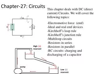
Chapter 27. Circuits 27.1. What is Physics? 27.2. "Pumping" Charges 27.3. Work, Energy, and Emf 27.4. Calculating the Current in a Single-Loop Circuit 27.5. Other Single-Loop Circuits 27.6. Potential Difference Between Two Points 27.7. Multiloop Circuits 27.8. The Ammeter and the Voltmeter
What is Physics? How can you maintain charges to flow?
“Pumping” Charges To produce a steady flow of charge, you need a “charge pump” (battery), a device that—by doing work on the charge carriers—maintains a potential difference between a pair of terminals. We call such a device an emf device, and the device is said to provide an emf ε , which means that it does work on charge carriers. The maximum potential difference between the terminals of the battery is called the electromotive force(emf)ε of the battery
Work, Energy, and Emf • Within the emf device, positive charge carriers move from a region of low electric potential and thus low electric potential energy. This motion is just the opposite of what the electric field between the terminals would cause the charge carriers to do. • there must be some source of energy within the device, enabling it to do work on the charges by forcing them to move as they do. The energy source may be chemical, as in a battery or a fuel cell. It may involve mechanical forces, as in an electric generator • Emf is:
emf device • An ideal emf device is one that lacks any internal resistance to the internal movement of charge from terminal to terminal. The potential difference between the terminals of an ideal emf device is equal to the emf of the device. • A real emf device, such as any real battery, has internal resistance to the internal movement of charge. When a real emf device is not connected to a circuit, and thus does not have current through it, the potential difference between its terminals is equal to its emf. However, when that device has current through it, the potential difference between its terminals differs from its emf.
If the current flows from the negative terminal to the positive terminal of the emf device, the other types of energy will be converted to electrical energy in the circuit; • If the current flows from the positive terminal to the negative terminal of the emf device, electrical energy in the circuit will be stored in the emf device as other types of energy.
Calculating the Current in a Single-Loop Circuit • LOOP RULE: The algebraic sum of the changes in potential encountered in a complete traversal of any loop of a circuit must be zero. • RESISTANCE RULE: For a move through a resistance in the direction of the current, the change in potential is −iR; in the opposite direction it is +iR. • EMF RULE: For a move through an ideal emf device in the direction of the emf arrow, the change in potential is +ε; in the opposite direction it is -ε.
Checkpoint The figure shows the current i in a single-loop circuit with a battery B and a resistance R (and wires of negligible resistance), (a) Should the emf arrow at B be drawn pointing leftward or rightward? At points a, b, and c, rank (b) the magnitude of the current, (c) the electric potential, and (d) the electric potential energy of the charge carriers, greatest first.
Resistances in Series • The same electric current through each device. • The sum of the potential differences across the resistances is equal to the applied potential difference V. V=V1+V2+V3. • Resistances connected in series can be replaced with an equivalent resistance Req that has the same current i and the same total potential difference V as the actual resistances.
Example:Resistors in a Series Circuit A 6.00-W resistor and a 3.00-W resistor are connected in series with a 12.0-V battery, as Figure 20.16 indicates. Assuming that the battery contributes no resistance to the circuit, find (a) the current, (b) the power dissipated in each resistor, and (c) the total power delivered to the resistors by the battery.
Resistances in Parallel • The same voltage is applied across each device • i=i1+i2 • The equivalent resistance is
Question In one of the circuits in the drawing, none of the resistors is in series or in parallel. Which is it? Explain.
Example 7 A 47.0 W and a 33.0 W resistor are connected in parallel. What is the equivalent resistance of the resistors? How much current would a 12.0 V battery supply to the network and how much current would flow through each resistor?
Potential Difference Between Two Points To find the potential between any two points in a circuit, start at one point and traverse the circuit to the other point, following any path, and add algebraically the changes in potential you encounter. The terminal-to-terminal potential difference V across the real battery is different from ε.
Sample Problem The emfs and resistances in the circuit of Fig. 27-8a have the following values: • What is the current i in the circuit? • b) What is the potential difference between the terminals of battery 1 in Fig. 27-8a?
Power, Potential, and Emf The energy transfer from the emf device to the outside charge carriers is
Multiloop Circuits KIRCHHOFF’S RULES: • Junction rule. The sum of the magnitudes of the currents directed into a junction equals the sum of the magnitudes of the currents directed out of the junction. • Loop rule. Around any closed-circuit loop, the sum of the potential drops equals the sum of the potential rises.
Sample Problem Figure 27-11a shows a multiloop circuit containing one ideal battery and four resistances with the following values: (a) What is the current through the battery? (b) What is the current i2 through R2?
Sample Problem Figure 27-12 shows a circuit whose elements have the following values: What are the magnitude and direction of the current in each of the three branches?
Conceptual Questions • The power rating of a 1000-W heater specifies the power consumed when the heater is connected to an ac voltage of 120 V. Explain why the power consumed by two of these heaters connected in series with a voltage of 120 V is not 2000 W. • A number of light bulbs are to be connected to a single electrical outlet. Will the bulbs provide more brightness if they are connected in series or in parallel? Why?