Download
1 / 26
260 likes | 280 Views
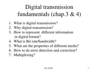
Learn about the basics of signal transmission, time-domain concepts, sine wave parameters, frequency-domain concepts, fundamental frequency, data vs signal, approximating square wave, data rate vs bandwidth, analog and digital signal conversion, channel capacity, Nyquist bandwidth, signal-to-noise ratio, and Shannon capacity formula.

E N D
Transmission Fundamentals Chapter 2 (Stallings Book)
Electromagnetic Signal • is a function of time • can also be expressed as a function of frequency • Signal consists of components of different frequencies
Time-Domain Concepts • Analog signal - signal intensity varies in a smooth fashion over time • No breaks or discontinuities in the signal • Digital signal - signal intensity maintains a constant level for some period of time and then changes to another constant level • Periodic signal - analog or digital signal pattern that repeats over time s(t +T ) = s(t ) -¥< t < +¥ where T is the period of the signal • Aperiodic signal - analog or digital signal pattern that doesn't repeat over time
Time-Domain Concepts (cont.) • Peak amplitude (A) • maximum value or strength of the signal over time • typically measured in volts. • Frequency (f ) • Rate, in cycles per second, or Hertz (Hz), at which the signal repeats.
Time-Domain Concepts (cont.) • Period (T) • amount of time it takes for one repetition of the signal • T = 1/f • Phase () - measure of the relative position in time within a single period of a signal • Wavelength () - distance occupied by a single cycle of the signal • Ex: Speed of light is v = 3x10⁸ m/s. Then the wavelength is f = v (or = vT).
Sine Wave Parameters • General sine wave • s(t ) = A sin(2ft + ) • note: 2 radians = 360° = 1 period • Figure 2.3 shows the effect of varying each of the three parameters • (a) A = 1, f = 1 Hz, = 0; thus T = 1s • (b) Reduced peak amplitude; A=0.5 • (c) Increased frequency; f = 2, thus T = ½ • (d) Phase shift; = /4 radians (45 degrees)
Frequency-Domain Concepts • An electromagnetic signal can be made up of many frequencies. • Example: s(t) = (4/p)x(sin(2pft) + (1/3)xsin(2p(3f)t)) • Fig. 2.4(a) + Fig. 2.4(b) = Fig. 2.4(c) • There are two component frequencies: f and 3f. • Based on Fourier analysis, any signal is made up of components at various frequencies, • in which each component is a sinusoid wave, at different amplitudes, frequencies, and phases.
Frequency-Domain (cont.) • Spectrum - range of frequencies that a signal contains • In Fig. 2.4(c), spectrum extends from f to 3f. • Absolute bandwidth - width of the spectrum of a signal • In Fig. 2.4(c), it is 3f – f = 2f. • Effective bandwidth – • A signal may contain many frequencies. • But most of the energy may concentrate in a narrow band of frequencies. • These frequencies are effective bandwidth.
Fundamental frequency – • when all frequency components of a signal are integer multiples of one frequency, it’s referred to as the fundamental frequency • (earlier example) f and 3f fund. freq = f • The period of the total signal is equal to the period of the fundamental frequency. • refer to Fig. 2.4 again!
Data vs. Signal • Signals - electric or electromagnetic representations of data • Data - entities that convey meanings or information • Transmission - communication of data by the propagation and processing of signals
Approximating Square Wave by Signals • adding a frequency of 5f to Fig. 2.4(c) Fig. 2.5(a) • adding a frequency of 7f to Fig. 2.4(c) Fig. 2.5(b) • adding all frequencies of 9f, 11f, 13f, ... Fig. 2.5(c), a square wave • This square wave has an infinite number of frequency components, and thus infinite bandwidth.
Data Rate vs. Bandwidth • Case I: (Fig. 2.5(a)) • Let f = 106 cycles/sec = 1 MHz • frequency components: 1f, 3f, 5f • absolute bandwidth = 5f – 1f = 4f = 4 MHz • data rate = 2 Mbps (1 bit per 0.5 us) • Case II: (Fig. 2.5(a)) • Let f = 2x10⁶ cycles/sec = 2 MHz • frequency components: 1f, 3f, 5f • absolute bandwidth = 10M – 2M = 8 MHz • data rate = 4 Mbps (1 bit per 1/4 us)
Case III: (Fig. 2.4(c)) • Let f = 2x10⁶ cycles/sec = 2 MHz • frequencies: 1f, 3f • absolute bandwidth = 6M – 2M = 4 MHz • data rate = 4 Mbps (1 bit per 1/4 us)
Some Terms about Channel Capacity • Data rate - rate at which data can be communicated (bps) • Bandwidth - the bandwidth of the transmitted signal as constrained by the transmitter and the nature of the transmission medium (Hertz) • Noise • Channel Capacity – the maximum rate at which data can be transmitted over a given communication path, or channel, under given conditions • Error rate - rate at which errors occur
Nyquist Bandwidth • Given a bandwidth of B, the highest signal transmission rate is 2B: • C = 2B • Ex: B=3100 Hz; C=6200 bps • With multilevel signaling • C = 2B log2M, where M is the number of discrete signal or voltage levels
Signal-to-Noise Ratio • Signal-to-noise ratio (SNR) • = power of signal/power of noise • typically measured at a receiver • Signal-to-noise ratio (in db) • A high SNR means a high-quality signal.
Shannon Capacity Formula • The max. channel capacity: • note: SNR not in db. • In practice, only much lower rates are achieved • Formula assumes white noise (thermal noise) • Impulse noise is not accounted for • Attenuation distortion or delay distortion not accounted for
Classifications of Transmission Media • Transmission Medium • Physical path between transmitter and receiver • Guided Media • Waves are guided along a solid medium • E.g., copper twisted pair, copper coaxial cable, optical fiber • Unguided Media • Provides means of transmission but does not guide electromagnetic signals • Usually referred to as wireless transmission • E.g., atmosphere, outer space
General Frequency Ranges • Microwave frequency range • 1 GHz to 40 GHz • Directional beams possible • Suitable for long-distance, point-to-point transmission • Used for satellite communications • Radio frequency range • 30 MHz to 1 GHz • Suitable for omnidirectional applications • Infrared frequency range • Roughly, 3x10¹¹ to 2x10¹⁴ Hz • Useful in local point-to-point multipoint applications within confined areas
Time-division multiplexing (TDM) Takes advantage of the fact that the achievable bit rate of the medium exceeds the required data rate of a digital signal Frequency-division multiplexing (FDM) Takes advantage of the fact that the useful bandwidth of the medium exceeds the required bandwidth of a given signal Multiplexing Techniques
Summary • signal • analog vs. digital transmissions • channel capacity • transmission media • TDM/FDM