Download
1 / 20
220 likes | 461 Views
FPGA System For Flash Memory Final Presentation. Project B, Winter 2013, HSDSL Lab, Technion Supervisor : Amit Berman Students : Baruh Nurilov Eyal Amir. Flash Overview. Very popular. Non-volatile. Small. Cheap. Uses. Disadvantages. Block erasure. Endurance. Errors.

E N D
FPGA System For Flash MemoryFinal Presentation Project B, Winter 2013, HSDSL Lab, Technion Supervisor: Amit Berman Students: BaruhNurilov Eyal Amir
Flash Overview • Very popular. • Non-volatile. • Small. • Cheap. • Uses.
Disadvantages • Block erasure. • Endurance. • Errors. * Micron NAND Flash memory - MT29F64G08CBAA - Datasheet
WOM Code • Write-Once Memory reuse. - Each n-bit codeword represents a k-bit word. - Guarantees at least t writes. * Ronald L. Rivest and Adi Shamir, “How to Reuse a ‘Write-Once’ Memory”, Information And Controll Vol. 55, Nos. 1-3, November 1982
Project Goal • Designing a controller for flash memory that implements reading, writing and erasing. • Measuring, using the above controller, the amount of errors generated by repeated write-erase cycles. • Assessing the potential advantages of using WOM codes in the writing process.
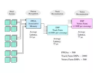
Overview Reading Writing Erasing Writing Saving Reading Data Generation Comparison
Block Diagram Main Controller PLL Flash Module SDRAM Module Flash Device SDRAM
The SDRAM Module SDRAM Interface We_i SDRAM Controller Dram_cke Stb_i Cyc_i Dram_clk Ack_u Ack_o Dram_cs_n Cmd_u Dram_ldqm Data_u_i Data_u_o Dram_udqm Addr_i Addr_u Dram_ras_n Dat_i Dat_o Dram_addr Dram_dq Dram_bank
The Flash Commands * Micron NAND Flash memory - MT29F64G08CBAA - Datasheet
The Flash Module Flash_wp_n_u Last_word_tb Flash Interface Flash Controller Flash_ce_n_u Flash_ce_n Next_word_tb Cmd_i Done_tb Flash_re_n Addr_i Word_done_tb Data_i Flash_we_n Cmd_tb Data_o Data_o_tb Cmd_ena Flash_ale Addr_ena Data_i_tb Data_in_ena Flash_cle Addr_tb Data_out_ena Flash_wp_n Cmd_done Addr_done Flash_r_nb Data_in_done Flash_dq Data_out_done Status_check Erase_address
The Flash Interface Cmd_ena Signal Controller Flash_ce_n Command FSM Current_state Cmd_done Flash_re_n Flash_we_n Addr_ena Address FSM Current_state Addr_done Flash_ale Data_in_ena Data-In FSM Flash_cle Current_state Data_in_done Flash_wp_n Data_out_ena Flash_r_nb Data-Out FSM Current_state Data_out_done Flash_dq
A Command Cycle * Micron NAND Flash memory - MT29F64G08CBAA - Datasheet
Flash Controller Last_word_tb Cmd_ena Signal Controller Next_word_tb Cmd_done Done_tb Read FSM enable Current_state done Word_done_tb Addr_ena Cmd_tb Program FSM enable Current_state Addr_done done Data_o_tb Data_i_tb User FSM enable Reset FSM Data_in_ena Current_state done Addr_tb Data_in_done Status FSM enable Current_state done Data_out_ena Erase FSM enable Current_state Data_out_done done
The Main Controller Last_word_tb SDRAM Controller Main Controller Flash Controller Next_word_tb Done_tb Word_done_tb Ack_u Cmd_u Cmd_tb Data_u_i Data_o_tb Data_u_o Data_i_tb Addr_u Addr_tb Data
Main Controller Last_word_tb Signal Controller Next_word_tb Done_tb Word_done_tb Ack_u Flash FSM Cmd_u Cmd_tb Current_state Data_u_i Data_o_tb Data_u_o Data_i_tb enable_n Main FSM tb_cmd Addr_tb Addr_u reset done SDRAM FSM Current_state get_data data_valid user_data
Results • On average ~350 errors per block after 3000 cycles. • On average ~2e-5 BER after 3000 cycles. • On average ~46.5 errors per block on first write.
Conclusions • k – bits to be written, n – bits after encoding, t – number of writes between erases, R - WOM-rate. * Scott Kayser, EitanYaakobi et al, “Multiple-Write WOM-Codes”, IEEE Transactions on Information Theory, 58 (9). pp. 5985-5999. ISSN 0018-9448.