Download
1 / 18
250 likes | 613 Views
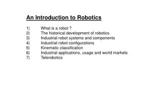
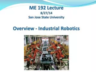
ISE 115 Lecture 2/5/14 Industrial Robotics. Anatomy. Similar to human torso, shoulder, arm, and wrist in construct, movement, and reach. Joints – Enables rotation of connected members. Provides the axes of rotation for adjoining members. Links – Rigid members between two joints.

E N D
Anatomy Similar to human torso, shoulder, arm, and wrist in construct, movement, and reach. Joints – Enables rotation of connected members. Provides the axes of rotation for adjoining members. Links – Rigid members between two joints.
Robot Joints & Links Groover Fig. 8.1 -8.2 Joints - Enables linear or rotational movement of adjoining members. Number of joints = Degrees of freedom • Linear (L) • Orthogonal (O) • Rotational (R) • Revolving (V) • Twisting (T) Lab SCARA: Revolving - Rotational - Orthogonal – Twisting Lab Cartesian: Linear – Linear – Orthogonal – Twisting Articulated Robot: Twisting – Rotational - Rotational Gripper Joints – Yaw (Z rotation), Pitch (Y rotation), Roll (X rotation)
Robot Configurations Groover Fig. 8.3-8.7 • Polar coordinate (T-R-L joints) • Cylindrical (L-R-R or L-V-R joints) • Cartesian (Rectilinear) (L-L-O joints) Reversal: • Articulated (Rotational, Jointed Arm) (T-R-R joints) • SCARA (V-R-O-T) Reversal: Tool Configuration: Rotation on Tool XYZ coordinates Yaw – Y axis Pitch – X axis Roll – Z axis
Applications & Set up Location Applications • Primary uses: Part pick & place, part presentation, transferring, visual inspection. • Solutions for: Hazardous conditions, tedium, ergonomic issues, positional accuracy, and precision. • Economic life: General purpose machine. Extension of useful life with attachment of a new end effecter. Set up Location • Fixed (Robot centered, In-line, Off-line). • On-track (Floor or Ceiling). Ex. Robotic clamp in press work. • Free roaming.
Robot Kinematics Degrees of Freedom – Same as number of joints 4-axes for assembly robots: SCARA (x, y, z, r) 6-axes for materialhandling robots: Articulated arm robot Base, links - θ1, θ2, θ3. Wrist: y, p, r (yaw, pitch, roll) Positioning Lead screws for linear move or belt- or direct-drive servo motors for joint rotation. Drive Power – Electric, hydraulic, pneumatic. Motor type: open loop (stepper) or closed loop (servo). Motion Control Servo motor for rapid rotation of the upper joints. Stepping motor for precision movement of the lower joints.
Robot Kinematics Coordinate Systems - Cartesian (World) - X, Y, Z. Polar (Joint) - θ1, θ2, θ3. Tool – (y, p, r) WristAssembly – Typical, 3 degrees of freedom (Fig. 8.8). Keyed flange for gripper connection. End Effecter (Gripper) – Electric, pneumatic, vacuum, magnetic. May have a separate coordinate controller. Movement Path – PTP, Straight or curved motion under robot control. Linear/circular interpolation under program control. Absolute vs. Relative (Cartesian: ΔX, ΔY, ΔZ; Rotational: Δ θ1, Δ θ2, Δ θ3) Set P1 = Trans (x, y, z, y, p, r); r: Gripper angle on X-Y Set P2 = P1: Trans (dx, dy, dz, , , dr); Δ offsets from P1
R-R Robot: Polar to X-Y Conversion Length/height: L0 = Shoulder, L1 = Upper arm, L2 = Elbow Angles (Relative): θ0 = Base pivot, θ1 = Upper arm , θ2 = Elbow r = L1 Cos θ1+ L2 Cos (θ1+ θ2) X = r Sin θ0 Y = r Cos θ0 Z = L0 + L1 Sin θ1+ L2 Sin (θ1+ θ2) Exercise: Develop an extension for a R-R-R robot.
Polar and Cartesian coordinates of T-R-R Robot z (X, Y, Z) Z θ2 L2 r = L1 Cos θ1+ L2 Cos (θ1+ θ2) [θ2< 0 for left elbow] X = r Cos θ0 Y = r Sin θ0 Z = L0 + L1 Sin θ1+ L2 Sin (θ1+ θ2) R L1 θ1 y r R L0 Y T (X, Y, 0) θ0 X x
Robot Operation - Features • Programming Tool – Teach (Lead-through path), Program code, Simulator/Code generator • Signal Interface – I/O ports for exchanging signals with other in-line equipment • Vision Guidance – Positioning, Gripper orientation, Gaging, Shape recognition, Part ID, OCR inspection • Safety Interlock – E-stop, motor stall sensor, light curtain, pull cord, enclosure
Robot Calibration • Start up Calibration – Automatic, upon power up. To check the accuracy and the precision (variation) in joint movement and breaking response. • Vision Calibration – One time, manual, for target areas. To set switches and parameters in image processing (such as threshold values for binary conversion, display option, brightness and contrast, filters for image size, etc.) To find the camera offset from the center of axis. Example of vector addition for calculating gripper location: grip.loc = pic.loc : cam.offset : obj.loc : grip.ang = ref.loc : obj.loc : grip.ang cam.offset can be manually generated. How?
Work Envelope The 3-D space reachable by end effecter - Sweep area. Safety Envelope – Additional 12” around the work envelope. Lab 550 Robot – Plan View
C.R., Accuracy, Repeatability Linear Positioning System Control Resolution Distance between two adjacent addressable points C.R. determined by mechanical limit Repeatability ± 3 σ (σ : mechanical error) Accuracy ½ of C.R. ± 3 σ Ex. Lead screw mechanism with gear driven by stepping motor XY bench on CNC machine, Z-axis drive on SCARA robot. Extension to XYZ rectilinear and θ1θ2θ3angular reach space.