Download
1 / 21
300 likes | 613 Views
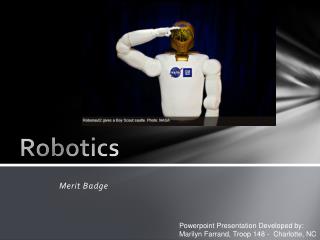
Lecture 2: Introduction to Concepts in Robotics. In this lecture, you will learn: - Basic Robotics Concepts Start discussion on geometric aspects: frames, positions, orientations. Homogenous transforms Some math recap. Robot Subsystems. A mechanical structure.

E N D
Lecture 2:Introduction to Concepts in Robotics In this lecture, you will learn: - Basic Robotics Concepts • Start discussion on geometric aspects: frames, positions, orientations. • Homogenous transforms • Some math recap
Robot Subsystems • A mechanical structure. • For manipulators this structure consists of a set of rigid bodies (links), connected by means of articulations (joints). Links and joints can also be described in terms of an arm (for mobility), a wrist (for dexterity) and an end-effector (for performing the task). • For mobile robots, the structure consists of a chassis with a locomotion mechanism, in the form of legs, wheels, rotor blades, etc. • Actuators. These set the robot in motion through actuation of its joints, and are typical electric or hydraulic. • Sensors. These measure the status of the manipulator (propriceptive sensors) and the status of the environment (heteroceptive sensors). • A control system. This enables control and supervision of the robot, and is usually a computer with a graphical user interface, and/or a pendant.
Typical Industrial Robot • 6 DOFs • Controller
Mechanics of Manipulators • We describe robotic manipulators in terms of their degrees of freedom (DOFs). • 6 DOFs are needed to position and orient an object in a unique way in the 3D space. • Most robots have no more than 6 degrees of freedom. If they do, they are called redundant robots. Redundant robots can be ideal for situations requiring reaching out behind certain obstacles. • The manipulator links are connected together in chains. Chains can be open or closed. • Manipulators with open chains are also called serial, while the ones with closed chains are called parallel. • Joints allow relative motion between links, and can be rotary (revolute – R ) or linear (prismatic –P ). • The workspace of the manipulator is the total volume swept out by the end-effector of the manipulator. • The workspace may be constrained by the fact that not all joints can rotate 360 degrees. • The workspace is defined in terms of point reachable with arbitrary orientations (dextrous workspace) or fixed orientations (reachable workspace).
Examples of industrial manipulator geometries Revolute “RRR”
Examples of industrial manipulator geometries Cartesian “PPP”
Examples of industrial manipulator geometries Spherical “RRP”
Examples of industrial manipulator geometries • “SCARA” • 3R+P
Examples of industrial manipulator geometries • Parallel • Stewart platform
Workspace Examples • Revolute
Workspace Examples • Cartesian, Scara
Properties of Manipulators • The most important considerations for the application of an industrial robot are: • Manipulator performance • System integration • Reconfigurability/modularity • Manipulator performance is defined as: • Reach (size of workspace), and dexterity (angular displacement of individual joints). Some robots can have unuseable workspace due to dead-zones, singular poses, wrist-wrap poses. • Payload (weight that can be carried). Inertial loading for rotational wrist axes can be specified for extreme velocity and reach conditions. • Quickness (how fast it can move). Critical in determining robot throughput but rarely specified. Maximum speeds of joints are usually specified, but average speeds while carrying payloads in a working cycle is of interest. • Duty-cycle (how fast it can repeat motions without breaking down).
Properties of Manipulators • Precision is defined by using 3 metrics: resolution, repeatability and accuracy. • These concepts are usually static, and dynamic precision is usually not specified. • Accuracy is defined as how close the manipulator can come to a given point within its workspace. • Accuracy varies with the location of the point • Repeatability is how close the manipulator returns to the same point in space. • Most present day manipulators are highly repeatable but not very accurate. • Repeatability for the manipulator is also defined as the ability to return to a so called “taught” position. • Resolution is defined as the minimum motion increment that the manipulator can perform and detect. • example: a robot controller has 12-bit storage capacity, the full range of the robot = 1.0 cm for one joint • spatial resolution = 1.0cm/212 = 1.0 cm/4096 = 2.44 µm
Basic Concepts • In robotics we are constantly concerned with the location of objects in 3D space. • In order to describe it we attach a coordinate frame rigidly to an object, or to the manipulator. We then transform the position and orientation from one frame to another. The frame associated with the non-moving parts of the manipulator is called the base frame, and the one attached to the end-effector is called the tool frame.
Basic Concepts • Kinematics is the science of motion based on geometric description, regardless of the forces which cause it. Kinematics deals with positions and its derivatives (velocity/acceleration). • The number of DOFs of the manipulator equals the number of independent position variables that would have to be specified in order to locate all parts of the mechanism. It equals the number of joints in an open kinematic chain. • Forward Kinematics refers to the problem of computing the position and orientation of the end-effector relative to the base frame given a set of joint angles. • Cartesian space (or task space, operational space) is the usual 3D Euclidian space for position and orientation (6 DOFs). The joint space (or configuration space) is the space in which the manipulator is described by it’s joint angles. • Inverse kinematics is the problem of inverse mapping between end-effector positions and orientation and the joint angles. We need to map locations in task space to the robot’s internal joint space. Early robots lacked this algorithm and they were simply “taught” joint spaces by moving the end-effector (by hand) to the desired position. The inverse kinematics problem is considerably harder than forward kinematics because it involves solving a non-linear equation which may not have a closed form solution. Also, no solution, or multiple solutions may exist.
Basic Concepts • The manipulator Jacobian is a matrix that relates the velocities of the joints to the velocities of the end-effector. When this matrix becomes singular (non-invertible), such points are called singularities. Example: WW I rear gunner. • Open chain manipulators are designed as a cascade of revolute or prismatic joints. They usually have up to six degrees of freedom depending on the task. For example a pick and place tasks from a 2D plane requires only 4 degrees of freedom. A welding operation on a car requires all 6 degreed of freedom. By using two manipulators to carry a load, one forms a closed kinematic chain. By using multiple kinematic chains, one can form much stiffer and precise robots called parallel manipulators. • Manipulators don’t always move through free space. They are sometimes required to touch a workpiece and apply a force. It turns out that we can use the manipulator Jacobian to calculate the relationship between joint torques and the forces exerted. • The joint actuators of the manipulators are electric or hydraulic motors used to create motion of the joints.
Basic Concepts • Dynamics is devoted to studying the forces required to cause motion. • The relationship between the joint actuator torques, the accelerations of the robot, and the other external forces (gravity of links and payload, external forces exerted) is studied within the context of dynamics. • Dynamics is important if we use high velocities to actuate the system. • If there is no motion involved, the force/torque balancing analysis is also called manipulator statics • Kinematics is usually sufficient if the robot is gravity compensated and moves at slow speeds. • Dynamics is necessary for simulation and control. • Motion planning refers to the study of generating motion for the robot to accomplish a task. This consists of : • Path planning - generating a feasible path from an initial position to a final position by describing the geometric position and orientation of the robot during the transition. Sometimes this path must avoid obstacles in the task space, and it may be described by intermediate points (also called via-points). Sometimes the path is a spline (e.g. a smooth function that passes through a set of via points). • Trajectory generation – attaching a time frame to the paths generates a trajectory. The trajectory not only describes the position of the robot during motion, but also how that position changes with time.
Basic Concepts • Manipulator control refers to a closed-loop feedback system that uses sensory information to control the motion of the manipulator. A controller accomplishes : • Trajectory tracking – following the prescribed trajectory for the manipulation. • End-point control - reaching a goal configuration in either task or joint space irrespective of the trajectory it is achieved. This is also called the stabilization problem. • Position/velocity control – compensates for errors in knowledge of the systems parameters and suppresses disturbances. Control algorithms can be linear or nonlinear. • Force control – Controlling the force exerted by the manipulator onto an object in a single or multiple degrees of freedom. Can be reduced to position control if the stiffness of the manipulator and object are known, but it usually requires force sensing. Sometimes a scheme called hybrid control is used, e.g. controlling force along certain DOFs and position along other DOFs. • Robot Programming – Modern robots use robot programming languages to describe tasks from users. Programming could be on-line (with the robot attached) and off-line (with a dynamic simulation model of the robot). The issue of safety should be carefully considered when implementing on-line robot motion. Often time robotic cells have interlocked protective enclosures and fences.
Robot Control Architectures 1) Functional (deliberative) vs. 2) Behavioral Model: 1) Sense-Think-Act cycle in serial mode with five “Think” functional modules: • Perception, Modeling, Planning, Task Execution, Motor Control. Internal model maintenance/update consumes resources. This model has problems with long reaction times. Symbols are used to represent knowledge and generate actions. This approach dominated robotics in the first 30 years.
Robot Control Architectures 2) Sense-Think-Act cycle is decentralized in parallel mode. Brooks proposes a subsumption architecture (1985) with 8 behaviors: - reason about objects, plan changes to world, identify objects, monitor changes, build maps, explore, wander, avoid objects. Advantages: quick reaction, multiple goals, no conflict resolution needs, easy to extend, debug, etc. Disadvantages: sub-optimal, not clear how to describe and implement complex plans.
Recap of Math Concepts • Vector space • Subspace • Vector norm • Matrix norm • Inner product • Groups • Special matrices • Eigenvectors, eigenvalues • Singular value decomposition