Download
1 / 23
230 likes | 510 Views
Sa ME 192 Lecture 8/27/14 San Jose State University Overview - Industrial Robotics. Anatomy. Similar to human torso, shoulder, arm, and wrist in construct, movement, and reach. Joints – Enables rotation of connected members. Provides the axes of rotation for adjoining members.

E N D
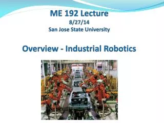
SaME 192 Lecture8/27/14San Jose State UniversityOverview - Industrial Robotics
Anatomy Similar to human torso, shoulder, arm, and wrist in construct, movement, and reach. Joints – Enables rotation of connected members. Provides the axes of rotation for adjoining members. Socket joints: Human (Shoulder and hip) Robot (Wrist – combined three rotational joints) Links – Rigid members between two joints.
Joints & Links Joints - Enables linear or rotational motion of adjoining members. Number of joints = Degrees of freedom • Linear (L) • Orthogonal (O) • Rotational (R) • Revolving (V) • Twisting (T) SCARA: Revolving -Rotational -Orthogonal –Twisting Cartesian: Linear –Linear –Orthogonal –Twisting Articulated 6-axis: Twisting –Rotational –Rotational-Y-P-R Yaw-Pitch-Roll: Wrist socket joint R-R-R Prismatic Revolute
Joint Types Prismatic Revolute
Link Length and Link Offset Six Axis SCARA Cartesian • Link Length = A link segment that is normal or radial with • respect to the axis of rotation or sliding. • Link Offset = A link segment that either coincides or is parallel • with the rotation or sliding axis of predecessor.
Configurations • Polar coordinate (T-R-L joints) • Cylindrical (L-R-R or L-V-R joints) • Cartesian (Rectilinear) (L-L-O joints) • Articulated (Rotational, Jointed Arm) (T-R-R joints) • SCARA (V-R-O-T) – Selectively Compliant Assembly Robot Arm Tool Configuration: Rotation on Tool XYZ coordinates Yaw – RY axis Pitch – RX axis Roll – RZ axis
Joint Framing – Class Convention Assignment of a XYZ Cartesian frame at each joint starting at the base and ending at the end effector. Using the right hand rule: • Align Zi(thumb) with the axis of rotation and with Zi-1 (the direction of sliding for prismatic joint) • Align Xi (index) with Xi-1, pointing at the next joint (Align with Zi+1 for prismatic joint) • Set Y to be orthonormal to the X-Z plane, • In prismatic joint, link length ai= 0 with variable displacement di • In twisting joint, link length ai= 0 and di > 0.
Applications & Set up Location Applications • Primary uses: Part pick & place, part presentation, transferring, visual inspection. Ex. : Conveyor line robots, Robot centered work cells • Solutions for: Hazardous conditions, tedium, ergonomic issues, positional accuracy, and precision. • Economic life: General purpose machine. Long useful life with tool change (end effecter). Set up Location • Fixed (Robot centered, In-line, Off-line). • On-track (Floor or Ceiling).
Kinematics Degrees of Freedom – Same as number of joints 4-axes for assembly robots: SCARA (x, y, z, r) 6-axes for material handling robots: Articulated arm robot Base, links - θ1, θ2, θ3. Wrist: y, p, r (yaw, pitch, roll) Positioning Lead screws for linear move or belt- or direct-drive servo motors for joint rotation. Drive Power – Electric, hydraulic, pneumatic. Motor type: Servo motor for rapid movement including leadscrew mechanism on linear joints. Gear: Serrated (timing) belt or direct drive. Motion Control Using encoders and pulse count. .
Kinematics - Continued Coordinate Systems - Cartesian (World) - X, Y, Z. Polar (Joint) - θ1, θ2, θ3. Tool – (y, p, r) WristAssembly – Typical, 3 degrees of freedom (yaw, pitch, roll). Three coinciding orthogonal reference frames Motion Control – Positional: Forward - Transformation of Joint values into XYZR gripper position. Obtained through rotation and translation of joint frames. Reverse - Transformation of XYZR gripper position into Joint values. Temporal: Linear and angular velocity and acceleration of joints Path Generation – Straight or curvilinear connecting preset via points.
Dynamics • Determination of joint torque needed to support the mass of the robot links, effect the velocity and acceleration of the links, gripper, and the work load. • Motion control base on the relationship between the torque applied to joint links and the linear and angular velocity and acceleration of the links. • Stationary position, non-drift balancing of the arm position with joint torque without applying the brake.
Programming (Ex. Adept V+) Path Generation - Using Teach Pendant Here P1, Here P2, etc. Program Instructions – Using C+ like language. Set D1 = Trans(10, 20, 30, , , 90) Move P1:D1 ;P1 offset by D1 Position Definition Set P1 = Trans (x, y, z, y, p, r); Cartesian coordinates. Set #P2 = #ppoint(θ1, θ2, θ3, y, p, r); Angular coord. Motion Commands (Ex.: a safe drop off) Appro P1, 50 / Move P1 / Openi / Delay 1 / Depart 50
R-R Robot: Polar to X-Y Conversion Length/height: L0 = Shoulder, L1 = Upper arm, L2 = Forearm Angles (Relative): θ0 = Base pivot, θ1 = Upper arm , θ2 = Forearm r = L1 Cos θ1+ L2 Cos (θ1+ θ2) X = r Sin θ0 Y = r Cos θ0 Z = L0 + L1 Sin θ1+ L2 Sin (θ1+ θ2) Exercise: Develop an extension for a R-R-R robot.
T-R-R Robot Coordinates z (X, Y, Z) Z θ2 r = L1 Cos θ1+ L2 Cos (θ1+ θ2) [θ2< 0 for left elbow] X = r Cos θ0 Y = r Sin θ0 Z = L0 + L1 Sin θ1+ L2 Sin (θ1+ θ2) L2 R L1 θ1 y r R L0 Y T (X, Y, 0) θ0 X x
Peripherals • Programming Tool – Teach (Lead-through path), Program code, Simulator/Code generator • Signal Interface – I/O ports for exchanging signals with other in-line equipment • Vision – Positioning, Gripper orientation, Dimensional gaging, Pattern recognition, Part ID, OCR inspection • Safety Interlock – E-stop, motor stall sennsor, light curtain, pull cord, enclosure. Safety is a big concern on industrial robots. Elaborate, redundant e-stop circuitries are built into a robot system.
Robot Vision Applications • Part ID by geometric shape or by prototype matching. • Compensation for location shift and orientation change. • Check for a date code, surface defects, and missing features. • Carrier number check for part routing control. Equipment Smart camera and software running on PC. Vintage CCTV camera with vision process PCB and software.
Robot Vision - Continued Image Processing • Take a snap shot and frame it into window –Frame Grab • Select objects in the window per criteria - Filtering • Convert gray scale image into binary- Thresholding • Enhance binary image: Erosion-Dilation– Morphology • Extract edges & identify the shape –Pattern Recognition • Subject the processed image to Pass/Fail test. • If pass, transform camera location to gripper location. • Perform pick up operation.
Work Envelope The 3-D space reachable by the end effecter. Safety Envelope – Additional 12” around the work envelope. Lab 550 Robot – Plan View
Control Resolution, Accuracy, Repeatability Linear Positioning System Control Resolution Distance between two adjacent addressable points C.R. determined by mechanical limit Repeatability (Precision) ± 3 σ (σ : Std. mechanical error) Accuracy ½ of C.R. ± 3 σ Ex. Lead screw mechanism with gear driven by stepping motor XY bench on CNC machine, Z-axis drive on SCARA robot. Robot Positioning System – Cylindrical, spherical Extension to XYZ rectilinear and θ1θ2θ3angular work space.