Parallel Pipeline Processors: Enhancing Throughput Efficiency
720 likes | 760 Views
Explore the cascade of linear processing stages, handshaking protocols, clock cycle management, and efficiency boosting techniques in pipeline processors. Understand reservation tables, latency analysis, collision vectors, state diagrams, and optimizing schedules in the dynamic pipeline architecture. Learn to optimize throughput while considering latency constraints and maximizing performance.

Parallel Pipeline Processors: Enhancing Throughput Efficiency
E N D
Presentation Transcript
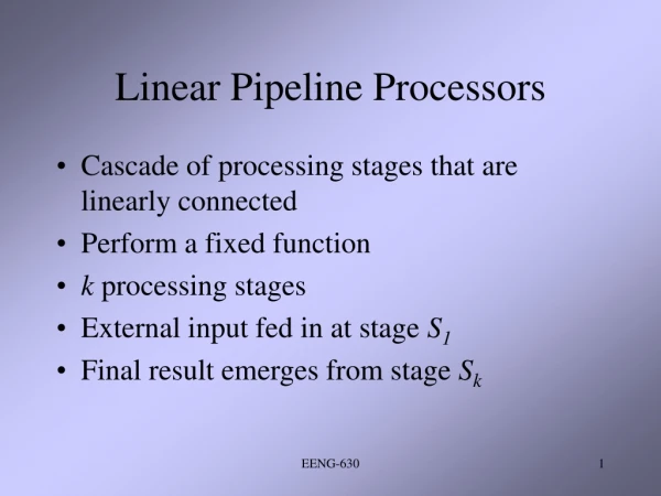
Linear Pipeline Processors • Cascade of processing stages that are linearly connected • Perform a fixed function • k processing stages • External input fed in at stage S1 • Final result emerges from stage Sk EENG-630
Asynchronous Model • Data flow between adjacent stages controlled by handshaking • Si sends ready signal to Si+1when ready to transmit • Si+1sends ack signal to Siafter receiving data • Allows variable throughput rate at stages EENG-630
Synchronous Model • Clocked latches used to interface between stages • Upon arrival of clock pulse, all latches transfer data to next stage • Approximately equal delay in all stages EENG-630
Reservation Table • Specifies utilization pattern of successive stages • Follows a diagonal streamline • Need k clock cycles to flow through • One result emerges at each cycle if tasks are independent of each other EENG-630
Clock Cycle • i = time delay of circuitry in Si • d = time delay of a latch • m = max stage delay • = m + d (clock cycle of pipeline) • Data latched to master f/f of each latch register at rising edge of clock pulse • d = width of clock pulse (m >> d) EENG-630
Pipeline Throughput • f = 1/ = pipeline frequency • At best, can expect one result per cycle, therefore, f represents the maximum throughput • Actual throughput < f due to initiation and dependencies EENG-630
Clock Skewing • Same clock pulse may arrive at different stages with time offset of s • tmax(tmin)= time delay of longest (shortest) logic path within a stage • Choose m > tmax + s and d tmin - s • d + tmax+ s m + tmin - s • Ideally s = 0, tmax = mand tmin = d EENG-630
Speedup Factor • Ideally k stage pipeline can process n tasks in k+(n-1) cycles • Tk = [k + (n –1)] • Flow thru delay = k for nonpipelined proc. • For n tasks: T1 = nk • Sk = T1/Tk = nk / [k+(n-1)] EENG-630
Number of Stages • Micropipelining: divide at logic gate level • Macropipelining: divide at processor level • Optimal # of stages should maximize performance/cost ratio • p = t/k + df = 1/p • Total cost = c + kh • PCR = f/(c+kh) = 1/(t/k + d)(c + kh) EENG-630
Efficiency and Throughput • Ek = Sk /k = n/[k +(n-1)] • Hk = n/[k + (n-1)] = nf / [k + (n-1)] • Max f when Ek 1 as n • Hk = Ek f = Ek / = Sk / k EENG-630
Dynamic Pipeline • Can be reconfigured to perform variable functions at different times • Allows feedforward/feedback connections • Making nonlinear pipelines • Linear pipelines are static for fixed functions • Following different dataflow patterns, can use same pipeline to evaluate different functions EENG-630
Reservation Tables • Multiple reservation tables can be generated for evaluation of different functions • Different fxns may follow dif. paths • One to many mapping b/t pipeline configuration and reservation tables • # of columns is evaluation time of a given fxn EENG-630
Latency • # of time units b/t two initiations • Any attempt by two or more initiations to use the same pipeline stage at the same time causes a collision – resource conflict • Forbidden latencies: cause collisions • To detect forbidden latencies, check distance b/t any two marks in the same row of the reservation table EENG-630
Latency Analysis • Latency sequence: sequence of permissible latencies b/t successive task initiations • Latency cycle: latency seq. that repeats the same cycle indefinitely • Average latency: divide sum of all latencies by # of latencies in cycle • Constant cycle: cycle which contains only one latency value EENG-630
Collision Vectors • Max forbidden latency m n-1 • Permissible latency: 1 p m-1 (p=1 ideal) • Collision vector: displays set of permissible & forbidden latencies (m bit binary vector) • Ci = 1 if latency i causes collision (0 else) • Cm = 1 always (max forbidden latency) EENG-630
State Diagrams • Specifies permissible state transitions among successive iterations • Initial collision vector: corresponds to initial state at time 1 • Next state at time t+p obtained w/m-bit right shift register • Next state after p shifts obtained by Oring initial collision vector w/shifted register EENG-630
Greedy Cycles • Simple cycles: each state appears only once • Some simple cycles are greedy cycles • One whose edges are all made w/min latencies from their respective starting states • Their average latencies must be lower than those of other simple cycles • One w/minimal avg. latency (MAL) chosen EENG-630
Bounds on MAL • Lower bounded by max # of checkmarks in any row of reservation table • Lower than or equal to avg. latency of any greedy cycle in the state diagram • Avg. latency of any greedy cycle is upper-bounded by # of 1’s in the initial collision vector + 1. (upper bound on MAL also) EENG-630
Optimizing Schedule • Greedy cycle not sufficient for optimality of MAL, lower bound is • Find lower bound by modifying the reservation table • Try to reduce max # of marks in any row • Modified table must preserve the original function being evaluated EENG-630
Delay Insertion • Use noncompute delay stages to increase pipeline performance with a shorter MAL • Purpose is to modify reservation table • Yields a new collision vector • Results in a modified state diagram EENG-630
Pipeline Throughput • Initiation rate or avg. # of task initiations per cycle • If N tasks initiated in n cycles, then initiation rate or pipeline throughput is N/n • Scheduling strategy affects performance • Shorter MAL, then higher throughput • Unless MAL reduced to 1, then throughput is a fraction EENG-630
Pipeline Efficiency • Stage utilization: % of time each stage is used over a long series of task initiations • Accumulated rate determines efficiency • Higher efficiency implies less idle time and higher throughput EENG-630
Instruction Execution Phases • Instruction execution consists of: • Fetch, decode, operand fetch, execute, and write back phases • Ideal for overlapped execution on a linear pipeline • Each phase may require one or more clock cycles to execute EENG-630
Instruction Pipeline Stages • Fetch: fetches instructions from cache • Decode: reveals the function to perform and identifies needed resources • Issue: reserves resources, maintain control interlocks, and read register operands • Execute: one or several stages • Writeback: write results into registers EENG-630
Prefetch Buffers • Three types of buffers can be used to match the instruction fetch rate to pipeline consumption rate • Sequential: for in sequence pipelining • Target: instructions from a branch target • Loop: seq. instructions within a loop • Fetch block of instructions in one memory access time to a prefetch buffer EENG-630
Multiple Functional Units • Bottleneck stage is one w/max # of marks in its row in the reservation table • Solve by using multiple copies of same stage simultaneously • Reservation stations for each unit used to resolve data or resource dependencies EENG-630
Reservation Stations • Operands wait in the RS until its data dependencies have been resolved • Each RS has an ID tag, monitored by a tag unit • Allows h/w to resolve conflicts b/t source and destination registers • Also serve as buffers EENG-630
Internal Data Forwarding • Improves throughput further • Replace some memory access ops by register transfer ops • Store-load forwarding: load replaced by move operation • Load-load forwarding: replace second load with move operation • Store-store: remove first store operation EENG-630
Hazard Avoidance • Read and write of shared variables by dif. instructions may lead to dif. results if executed out of order • Three types of hazards • RAW, WAW, and WAR • Domain = input set • Range = output set EENG-630
Hazard Conditions • RAW: R(I) D(J) (flow) • WAW: R(I) R(J) (antidependence) • WAR: D(I) R(J) (output) • Necessary, but not sufficient conditions • Occurrence depends on order two instructions are executed • Special tag bit used with each operand register to indicate safe or hazard-prone EENG-630
Static Scheduling • Data dependencies create interlocked relationship b/t sequence of instructions • Resolve by compiler-based static scheduling approach • Increases separation b/t interlocked instr. • Cheaper to implement and flexible to apply EENG-630
2 Add R0, R1 1 Move R1, R5 2 Load R2, M(a) 2 Load R3, M(b) 3 Mult R2, R3 (multiply held up by previous load) Load R2, M(a) 2-3 Load R3, M(b) 2 Add R0, R1 2 Move R1, R5 1 Mult R2, R3 3 (no delay for multiply) Static Scheduling EENG-630
Tomasulo’s Algorithm • Hardware dependence-resolution scheme • Resolves resource conflicts as well as data dependencies using register tagging • An issued instruction whose operands are not available is forwarded to an RS associated w/the unit it will use EENG-630
CDC Scoreboarding • Dynamic instruction scheduling hardware • Scoreboard unit keeps track of registers needed by instructions waiting for units • When all registers have valid data, the scoreboard enables execution • When finished, resources are released EENG-630
Branching Terms • Fetching a nonsequential instruction after a branch instr. is called branch taken • Instr. to be executed after a branch taken is called branch target • # of cycles b/t branch taken and its target is called delay slot (denoted by b) EENG-630