Download
1 / 10
100 likes | 236 Views
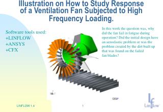
Illustration on How to Study Response of a Ventilation Fan Subjected to High Frequency Loading. In this work the question was, why did the fan fail in fatigue during operation? Did the initial design have an aeroelastic problem or was the problem created by the dirt built up

E N D
Illustration on How to Study Response of a Ventilation Fan Subjected to High Frequency Loading. In this work the question was, why did the fan fail in fatigue during operation? Did the initial design have an aeroelastic problem or was the problem created by the dirt built up that was found on the failed fan blades? Software tools used: +LINFLOW +ANSYS +CFX LINFLOW 1.4
CFX and the Ventilation Fan Analysis CFX (Navier-Stokes solver) used for calculation of unsteady pressure around the fan, which is the load exciting the fan. Flow Outlet CFX Velocity contours Rotor and stator details Flow Inlet LINFLOW 1.4
CFX Unsteady Pressure Up-stream the Fan. CFX used for calculation of unsteady pressure on the fan, which is the load exciting the fan. An FFT analysis gave the frequency spectrum of the load that the fan blades are subjected to. Time history of unsteady Pressure that fan blades see. LINFLOW 1.4
The ANSYS Structural model of the Ventilation Fan ANSYS Structural Model of the Fan To perform an aeroelastic stability and response analysis, a structural dynamics model is needed. In this case the ANSYS FE-program was used to develop the needed model. LINFLOW 1.4
The ANSYS Structure Dynamics Used by LINFLOW ANSYS Modal Results for the Fan LINFLOW 1.4
The LINFLOW Aeroelastic Model of the Fan • The LINFLOW linearized • fluid dynamics model of the • fan include both the fan blade • and a wake model. LINFLOW • uses boundary elements to • descretize the fluid dynamics, • which means that no flow domain • grid is needed. • Flow Conditions in this case: • Pressure = 5530 PaDensity = 1.2 kg/m3 • Angular Velocity = 870 – 920 rpm • Cp/Cv = 1.4 • Blade angle of attack 63o LINFLOW 1.4
LINFLOW Steady Fluid Dynamics • In LINFLOW the aeroelastics is • studied around some mean steady • flow condition. In this case we check • that the lift on the blade corresponds to • the force driving the flow through the • fan and that the drag on the blade • Corresponds to the moment that • the fan is driven by. Picture show velocity contours on the surface of the blades.. LINFLOW 1.4
LINFLOW Aeroelastic Stability Anlysis of the Fan. Aeroelastic Stability Check of the Fan Aeroelastic Frequencies a.f.o. Flow Velocity. Damping requirement for neutral stability for the 5 first modes in table 1. The calculation show no sign of aeroelastic stability problem In the RPM range at which the fan is operated. LINFLOW 1.4
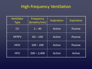
LINFLOW Response/Spectrum analysis, 1 LINFLOW Aeroelastic Response Analysis of the Fan with Clean Blades. Imaginary part of the stress field on the model Real part of the stress field on the model Spectrum analysis with SRSS summation gave 19.4 Mpa stress level in the root of the blade shaft. Measurements on clean blade gave approx. 20 Mpa stress level at the same location LINFLOW 1.4
LINFLOW Response/Spectrum analysis, 2 LINFLOW Response Analysis of the Fan with Dirt build-up on the blades. Real part of the stress field on the model Imaginary part of the stress field on the model Spectrum analysis with SRSS summation gave 32.0 Mpa stress level in the root of the blade shaft. This is above the 27 Mpa stress level that is the limit above which fatigue problems start to appear. Conclusion, the reason for failure was that the dirt built-up had changed the aeroelastic charactiristics so that vibration amplitude due to subjected load increased to levels above the fatigue limit for the material. LINFLOW 1.4