Download
1 / 18
180 likes | 288 Views
Semi-active Management of Structures Subjected to High Frequency Ground Excitation. C.M. Ewing, R.P. Dhakal, J.G. Chase and J.B. Mander 19 th ACMSM, Christchurch, New Zealand, 2006. The Scene. Structures can be highly vulnerable to a variety of environmental loads

E N D
Semi-active Management of Structures Subjected to High Frequency Ground Excitation C.M. Ewing, R.P. Dhakal, J.G. Chase and J.B. Mander 19th ACMSM, Christchurch, New Zealand, 2006
The Scene • Structures can be highly vulnerable to a variety of environmental loads • These days, man-made events can also have significant impact on the life, serviceability and safety of structures, and must be accounted for in new designs • i.e. blast loads • However, what do you do about already existing and potentially vulnerable structures? • In particular, how do you manage to protect the structure without overloading shear or other demands? • Particularly true for relatively older structures • Semi-active methods offer the adaptability to reduce response energy without increasing demands on the structure, but add complexity • Passive methods offer simplicity and ease of design, but are not adaptable or as effective.
Horizontal 50 m May cause sudden collapse. Impulsive nature. Post-BIGM response is also important. Large amplitude (~100 g) Short duration (<0.05 sec) Characteristics of BIGM Typical Seismic excitation Typical BIGM
Characteristics of BIGM Typical Seismic excitation Typical BIGM Horizontal 50 m May excite high frequency vibration Modes during major shock duration. High frequency (~200 Hz)
Impulse Shock Spectra • If t1/T < critical (0.4-0.5), - The maximum response of a linear structure depends on t1/T.
T = 1 sec Impulse-Response Relationship • If t1/T < critical (0.4-0.5), • The maximum response factor is proportional to the total energy applied, regardless of the impulse shape.
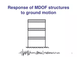
A Simple Structure & Damage 450kN live • Loads are impulsive • Excite higher order modes • Plastic first peak response is not unusual • Plastic deformation on return or second peak response may also occur • After initial pulse the response is transient free response from a large initial value • Main forms of damage: • Residual deformation • Low cycle fatigue Blast load based on pressure wave and face area 630kN live 1000kg/story E = 27GPa
General Dynamic Response Fundamental local modes Fundamental global mode Higher order global mode Frequency increases Acceleration increases Displacement decreases
P More Detailed Model Basic Elements: • Multiple elements per column to capture higher order responses [Lu et al, 2001] • Mass discretised over all elements in column • Blast load discretised to each storey based on pressure wave and face area • Simple frame used to characterise basic solutions available for something more complex than a SDOF analysis • Non-linear finite elements (elastic-plastic with 3% post yield stiffness) • Fundamental Period = 1 sec • Main structure model captures all fundamental dynamics required for this scenario
Typical Load • Short duration impulse (< T1/5) • Any shape will give the same result, as the basic input is an applied momentum • Provides an initial displacement • Pblast = 350kPa pressure wave • Triangular shaped pulse of duration Dt = 0.05 seconds or 5% of fundamental structural period
Typical Uncontrolled Response • A first large peak that is plastic • Second and third peaks may also have permanent deformation • Free vibration response after initial pulse (not linear) • Residual deformation Permanent deflection may be larger or even negative depending on size of the load
Tendon in shape of moment diagram Resetable device 1st floor Possible Solutions • Passive = Tendons • Restrict first peak motion = initial damage • Add slightly to base shear demand on foundation • Match overturning moment diagram [Pekcan et al, 2000] • Tendon yields by design during initial peak • Semi-Active = Resetable devices using 2-4 control law • Do not increase base shear • Reduce free vibration response = subsequent damage • Therefore, in combination these devices are designed to reduce different occurrences of damage in the response • However, can devices hooked to story’s manage damage for this case characterized by higher column mode response? • Paper also considers device on 2nd story and from ground to 2nd story
End Cap Seal Cylinder Piston Becoming A Proven Technology More later in conference from Mulligan et al, Rodgers et al and Anaya et al on resetable devices and semi-active applications/experiments
Viscous Damper Resist all velocity Resist all motion Reset at peaks 1-4 Resetable Resist motion away from 0 From 0Peak 1-3 Resetable Resist motion toward 0 From Peak0 2-4 Resetable Semi-Active Customised Hysteresis 1 3 4 2 Only the 2-4 control law does not increase base-shear
a) Valve b) Valves Cylinder Piston Cylinder Piston The Very Basic Ideas Independent two chamber design allows broader range of control laws
Specific Results • Device on first floor and tendon versus uncontrolled • First peak and free vibration reduced ~40-50% • 1st story response Displacement Time
Device Stiffness is Critical • Results normalised to uncontrolled response • Device stiffness in terms of column stiffness k • 50-100% of column stiffness = good result in free vibration per [Rodgers et al, 2006] Response Energy 2-norm 1st Peak 2nd Peak
Conclusions • Blast can be completely represented by the applied momentum rather than shape, pressure or other typically unknown values • Simple robust system shows potential in this proof of concept study on an emerging problem of importance for structural designers • Complexity added is minimal • Results show that significant improvements that could be critical to safety and survivability can be obtained • Minimal extra demand on foundations makes it particularly suitable for retrofit of existing (relatively older) structures