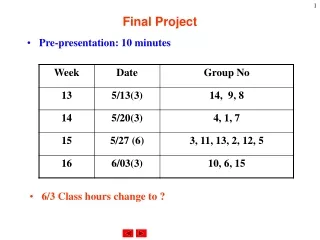
EE577b Fall2001 Final Project
This document presents a comprehensive overview of Finite Impulse Response (FIR) filters, including their mathematical representation, design considerations, and implementation details in a programmable architecture. It describes the basic operational principles of FIR filters, such as linear phase shifting and the significance of digital representation in both signed-magnitude and fixed-point formats. Key advantages and disadvantages are analyzed, alongside specific examples of arithmetic operations. The focus is on optimizing performance for low-power applications while addressing hardware complexity, particularly in digital signal processing designs. ###

EE577b Fall2001 Final Project
E N D
Presentation Transcript
EE577b Fall2001 Final Project Programmable FIR Filter Design Draft #1 (10/25/2001) Prof. Peter A. Beerel
What is FIR Filter? • FIR (Finite Impulse Response) Filter • A generalization of the moving window on the flow of data • Let the number of samples in the window be N • Weighted sum of last N samples • Weights given by N coefficients • Output zero after N successive samples of zero input
FIR Filter Mathematical Representation • It is convolution between input data and coefficients. • Linear phase-shift FIR filter • FIR filters with a symmetric set of coefficients • Benefits of Linear phase-shift FIR filter • The phase shift goes linearly with frequency • In typical low-pass filters, overall distortion is limited • Disadvantage of FIR filters • Major disadvantage of FIR filter is that the width of window is larger than IIR filter for similar frequency response
Top Diagram x0..x8,y0..y8 Dual-Rail Channels Signed magnitude fix-point representation x8, y8: sign x7, x6, y7, y6 integer field x0, x1, x2, x3, x4, x5, y0, y1, y2, y3, y4, y5 fraction field First 7 y outputs of each packet are garbage cmd 1’b01: read 8 coefficient on x, h0 through h7 1’b10: read packet of inputs [32 samples] & run Trojan FIR Filter Spec (Async)
Top Diagram X[8:0], Y[8:0] Signed magnitude fix-point representation [8]: sign [7,6] integer field [5,0] fractional field First 7 y outputs of each packet are garbage Cmd (L and K user-defined) 1’b01: read 8 coeffs on x h0 through h7 Each input sample holds for L clocks 1’b10: read packet of inputs [32 samples] Each input sample holds for K clocks 1’b11: idle Trojan FIR Filter Spec (Sync)
Signed-Magnitude Fixed-Point Representation • x = (-1)x[8]*(x[7]21+x[6] 20+x[5]2-1+…x[0]2-5) • 111111111 = (-1)*(11.111111)b=(-3.984375)d • Fixed-Point: • Can maintain good precision with adequate rounding scheme • Much simpler hardware than Floating-Point • Signed-Magnitude • Can use unsigned multiplier • Adder (Accumulator) will be more complex • Switching activity for synchronous single-rail design is smaller (-1 to 1) • 2’s complement : 11111111 to 00000001 (7 bits flip) • Signed-magnitude: 10000001 to 00000001 (1 bit flips) • Quantitative study shows that many subsequent values are changing around zero • Attractive characteristic for low-power single-rail logic • No advantage for asynchronous dual-rail adder
Signed-Magnitude Arithmetic • Addition/Subtraction • Need absolute value generation • 0,01.00000 + 1,01.11111 (-1.96875+1=-0.96875) • We want to get 1,00.11111 as a result • But conventional 2’s complement adder don’t • 01.00000 – 01.11111 = 11.00001 (oops!) • So, calculate both A-B,B-A and choose the positive number if two operands differ the sign bit. • If two operands differ the sign bit, addition becomes subtraction in signed-magnitude arithmetic. • If both operands have the same sign, operation will be addition not subtraction. (Choose any of them, it’s ok.)
Signed-Magnitude Arithmetic • Multiplication • In 2’s complement representation, multiplication is a bit complex than you think. -1 x 1 1111 x 0001 1111 0000 0000 0000 00001111 = 15 (not -1) • Therefore array multiplier will not work!
Signed-Magnitude Arithmetic • Multiplication (continued) • Solution for 2’s complement • Sign extension for each partial product: will make multiplier array much bigger • Use Baugh-Wooley multiplier: can reduce sign-extension bits significantly – very popular algorithm for DSP hardware • Good news for signed-magnitude is that integer and fraction parts are unsigned. • Can use unsigned multiplier (array multiplier) • Sign bit manipulation is easy (+) x (-) = (-), etc.
Fixed-Point Arithmetic • Range of coefficient • -1.0000000 =< h[k] <= 1.0000000 • One bit is integer and seven bits are fraction (MSB is sign bit) • Range of input and output • -11.111111b < x/y[n] < 11.111111b • Need 8x8 multiplier (3 integer, 13 fraction field) • Need 16-bit accumulator (3 integer, 13 fraction) • Keep full 16-bit precision for intermediate results • Watch out overflow! We will use saturated arithmetic. • Saturated arithmetic: overflow sets output to maximum value (1,11.111111 or 0,11.111111) • For final value, rounding is required (make even if tie)
Fixed-Point Arithmetic • “Make even if tie” rounding • Out of 16-bit intermediate result, we pick two integer field and 6 fraction field with sign bit. • S I I I . F F F F F F X X X X X X X • If XXXXXXX = 1000000, round up or truncate have the same round-off error. In this case, round up only if the final result after rounding becomes even number. • 0 001.111111 1000000=>round up=>0 010.000000 (even) • 0 001.000000 1000000=>truncate=>0 001.000000 (even) • If XXXXXXX = 0xxxxxx, truncate • If XXXXXXX = 1xxxxxx (at least one of x’s is 1), round up
Front-End Deliverables • 2 weeks (Nov 14th) • Async Teams (1-4 people) • Cell-based design • Structural down to cells • Behavioral verilog for each cell • Simple estimated delay model • Slack matching not necessary • Testbench complete • Initial correct streams (given to you next week) • Final input streams to be given in last week
Front-End Deliverables • 2 weeks (Nov 14th) • Sync Teams (1-4 people) • RTL design • Separate FSM Verilog and Datapath components • Routing logic (mux), pipeline registers, counters explicit • FSM design • Separate next-state, output logic, and state memory verilog processes • Explicit control signals • Behavioral verilog for each datapath component • Simple estimated delay model • Testbench complete • Initial correct streams (given to you next week) • Final input streams to be given in last week
Front-End Deliverables • 2 weeks (Nov 14th) Common Deliverables • Cadence schematics • Verilog code for all blocks • Verilog sims • Report • Architectural description and all assumptions • Performance estimation • Breakdown of work within team members
Back-End Deliverables • Common Deliverables (Dec 10th) • Critical path analysis • Justification of critical path / cycle • Wire load estimation • Transistor sizing of critical path (or critical cycle) • Hspice of critical path • Magic layout of critical path (or critical cycle) • Size estimation • HSPICE of extracted layout (no resistance extracted) • Floorplan • Size estimation of key blocks and of entire core • Report • Architecture update / revisions • Description of back-end efforts
Presentation • 5 minutes + 5 * # of team members • Overview of front and back-end designs • Same time as would be final exam • Grading • 30% Front-End Report • 40% Final Report • 30% Presentation