Download
1 / 23
240 likes | 434 Views
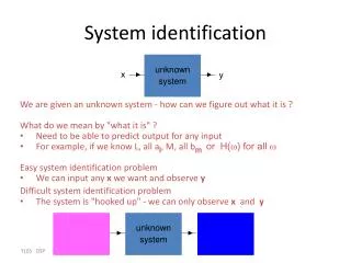
System Identification of a Nanosatellite Structure. Craig L. Stevens, Jana L. Schwartz, and Christopher D. Hall Aerospace and Ocean Engineering Virginia Tech Blacksburg, Virginia. Session 7, Earth and Lunar Missions AAS/AIAA Astrodynamics Conference Quebec City, Canada

E N D
System Identification of a Nanosatellite Structure Craig L. Stevens, Jana L. Schwartz, and Christopher D. Hall Aerospace and Ocean Engineering Virginia Tech Blacksburg, Virginia Session 7, Earth and Lunar Missions AAS/AIAA Astrodynamics Conference Quebec City, Canada July 30 – August 2 2001
Overview 3 2 • Introduction • Design • Analysis • Fabrication • Testing • Conclusions 4 5
Introduction • Virginia Tech Ionospheric Scintillation Measurement Mission (VTISMM) aka HokieSat • Ionospheric Observation Nanosatellite Formation (ION-F) • Utah State University • University of Washington • Virginia Tech • University Nanosatellite Program • 2 stacks of 3 satellites • Sponsors: AFRL, AFOSR, DARPA, NASA GSFC, SDL University Nanosatellites AFRL Multi-Satellite Deployment System (MSDS) NASA Shuttle Hitchhiker Experiment Launch System (SHELS)
Mission 3CS ION-F USUSat Dawgstar HokieSat Configuration: Multiple Satellite Deployment System Scenario:
Design HokieSat • 18.25” major diameter hexagonal prism • 12” tall • 39 lbs (~18 kg) • Isogrid Structure • Aluminum 6061 T-651 • Composite Side Panels • 0.23” isogrid • 0.02” skins
Design External Configuration Solar Cells Crosslink Antenna GPS Antenna LightBand Pulsed Plasma Thrusters Data Port Camera Uplink Antenna Downlink Antenna Science Patches
Design Internal Configuration Crosslink Components Cameras Power Processing Unit Torque Coils (3) Magnetometer Camera Pulsed Plasma Thrusters (2) Camera Battery Enclosure Downlink Transmitter Electronics Enclosure Rate Gyros (3)
Static Analysis • Requirement: Withstand ±11.0 g accelerations (all directions) • Margin of Safety 0, where • Factor of Safety (FS) • Finite Element Analysis Results
Dynamic Analysis Finite Element Analysis of Isogrid Side Panel (Without Skin) Mode 1 fn = 131 Hz Mode 2 fn = 171 Hz
Dynamic Analysis Finite Element Analysis of Complete Isogrid Structure (Without Skin) Mode 1 fn = 249 Hz
Dynamic Analysis Finite Element Analysis of Complete Isogrid Structure (Without Skin) Mode 2 fn = 263 Hz
Dynamic Analysis Finite Element Analysis of Complete ION-F Stack • Requirement: First mode natural frequency: >100 Hz • Results: First mode natural frequency: 74.6 Hz • Solution: Stiffen joints around attachment points to raise first mode natural frequency ~100Hz
Fabrication Composite structure comprised of 0.23” isogrid and 0.02” skin
Test Requirements • Static test • Stiffness test to simulate expected loading conditions during launch • Sine sweep test • Vibration test to determine free and fixed-base natural frequency • Sine burst test • Vibration test to verify structural strength at extreme loads • Random vibration test • Vibration test to verify structural integrity • Random Vibe Requirements:
Static Testing Strength & stiffness test of structure without skin panels Strength & stiffness test of loading fixture
Static Testing Strength & stiffness test of structure with skin panels • Experiment demonstrated a 32% gain in • stiffness in the cantilever mode due to addition of skins • Skins added less than 8% to the total mass
Dynamic Testing Modal (tap) Testing of Side Panels • Hammer provides impulsive input • Accelerometer measures accelerations used to characterize natural frequencies • Tap testing with and without skins • Verification of predictions of finite element analysis
Dynamic Testing Modal Testing of Side Panels (Without Skin) Mode 1 fn = 131 Hz (vs 131 Hz predicted) Mode 2 fn = 169 Hz (vs 171 Hz predicted)
Dynamic Testing Modal Testing of Side Panels (With Skin) Mode 1 fn = 213 Hz (vs 131 Hz without skin) Mode 2 fn = 453 Hz (vs 169 Hz without skin)
Dynamic Testing Modal Testing of Structure (Without Skins) Mode 2 fn = 272 Hz (vs 263 Hzpredicted) Mode 1 fn = 245 Hz (vs 249 Hz predicted)
Dynamic Testing Z Y X Accelerometer Placement • X-axis control • Y-axis control • Z-axis control • Side panel 1 • Side panel 2 • Zenith panel • GPS (3 axis) • CPU (3 axis) • PPU (3 axis) • Battery box (3 axis) • Structure survived • all tests • Determined component locations to raise natural frequencies
Conclusions • Aluminum isogrid increases structural performance at reduced mass • Modal testing verifies accuracy of isogrid side panel finite element model within ~1% error • Modal testing demonstrates 26% increase in structural stiffness of side panel by adding thin aluminum skins • Analyses and experiments verify structure satisfies all Shuttle payload requirements
Acknowledgements • Air Force Research Laboratory • Air Force Office of Scientific Research • Defense Advanced Research Projects • Agency • NASA Goddard Space Flight Center • NASA Wallops Flight Facility Test Center • University of Washington • Utah State University • Virginia Tech • Professor A. Wicks • Professor B. Love • Members of ION-F