Download
1 / 34
360 likes | 738 Views
Explore the fundamentals of impedance, tools of the trade, and applications like studying ionic conductors and electrode kinetics.

E N D
Impedance spectroscopy- with emphasis on applications towards grain boundaries and electrodics Harald Fjeld Department of Chemistry, University of Oslo, FERMiO, Gaustadalléen 21, NO-0349 Oslo, Norway NorFERM-2008, Gol
Outline • What is impedance? • Passive electrical circuit elements and their characteristics • Impedance spectroscopy • Tools of the trade • Impedance spectrometers • Softwares for fitting of data • Applications • Grain boundaries in ionic conductors • Electrodics NorFERM-2008, Gol
Worth to remember A R: resistance, unit: W r: resistivity, W cm C: capacitance, F e: permittivity, F cm-1 L NorFERM-2008, Gol
What is impedance? • Impedance is a general expression for electrical resistance, mostly used for alternating currents • For a sinusoidal current, the voltage is given according to U = U0 sin wt ..and the following current is given according to I = I0 sin (wt + q) t: time f: frequency w: angular frequency = 2pf wt: phase angle q: phase shift NorFERM-2008, Gol
What is impedance? X Z q R • Impedance is a general expression for electrical resistance, mostly used for alternating currents • From Ohm’s law, the impedance is given by the ratio of voltage and current. This equals the magnitude of the impedance, Z, when represented in a two-dimensional room spanned by real and imaginary vectors. In addition, we also want to know the phase shift (q) Z*(w) = Z’ + j Z’’ = ZRe+jZIm = R + j X Nyquist plot / Cole-Cole plot NorFERM-2008, Gol
Admittance • Instead of impedance, we may use the inverse, i.e. admittance Z: impedance Y: admittance R: resistance G: conductance X: reactance B: suceptance Z*(w) = R + j X Y*(w) = G + j B NorFERM-2008, Gol
Passive electrical circuit elements • An alternating current can be phase shifted with respect to the voltage • The phase shift depends on what kind of sample the current passes • To describe the response from a sample on the alternating current, we introduce 3 passive circuit elements (R, C and L) • The current and voltage through a resistor, R, is not phase shifted the impedance is not dependant on frequency • A resistor only contributes to the real part of the impedance NorFERM-2008, Gol
The capacitor • The capacitor, C, can store electrical charges e: permittivity e0: permittivity of free space er: relative dielectric constant • Only contributes to the imaginary part of the impedance NorFERM-2008, Gol
The inductor • As opposed to the capacitor, which is an ideal isolator, the inductor is an ideal conductor • Only contributes to the imaginary part of the impedance NorFERM-2008, Gol
The (RQ) circuit • Constant phase elements (CPE) may be regarded as non-ideal capacitors defined by the constants Y and n, and their impedance is given according to • The CPE is very versatile (“a very general dispersion formula”): • If n = 1, the CPE represents an ideal capacitor • If n = 0, the CPE represents a resistor • If n = -1, the CPE represents an inductor • If n = 0.5 the CPE represents a Warburg element Peak frequency: w0 = (RC)-1 Constant phase element NorFERM-2008, Gol
Impedance spectroscopy in solid state ionics • What: A technique for studying the conductivity of ionic conductors, mixed conductors, electrode kinetics and related phenomena • Features: • Eliminates the need for non-blocking electrodes • The impedance due to grain interiors, grain boundaries and different electrode properties can be measured independently • How: • A small AC voltage (e.g. 10 mV – 1 V) is imposed on the sample over a wide range of frequencies (e.g. 1 MHz – 0.1 Hz), and the complex impedance is measured NorFERM-2008, Gol
Real impedance spectra The spectrum can be fitted by using: NorFERM-2008, Gol
Tools of the trade • Solartron 1260 • Freq. range: 10 µHz – 32 MHz • Input impedance: 1 MW • DC bias: up to 41 V • AC amplitude: 5 mV – 3 V (rms) • Prize (2008): ~ 40 k€ • Considered as the state-of-the-art impedance spectrometer • Options: can be combined with a potentiostat (1287) or a high impedance interface (1296) NorFERM-2008, Gol
Tools of the trade • HP 4192A • Out of production since 2001, replaced by 4294A (4192A has been observed for sale at ebay) • Freq. range: 5 Hz – 13 MHz • Input impedance: 1 MW • DC bias: up to 40 V • AC amplitude: 5 mV – 1.1 V (rms) NorFERM-2008, Gol
Tools of the trade • Novocontrol alpha-A • Can be equipped with different test interfaces for different purposes (in Oslo: ZG4) • Freq. range: 30 µHz – 20 MHz • Input impedance: 1 TW • DC bias: up to 40 V • AC amplitude: 0.1 – 3 V (rms) • Prize (2008): ~ 35 k€ Mainframe ZG4 test interface NorFERM-2008, Gol
Tools of the trade • Hioki 3522-50 • A cheap, but OK alternative for ”standard tasks”? • Freq. range: 1 mHz – 100 kHz (+DC) • Input impedance: 1 MW?? • DC bias: up to 10 V • AC amplitude: 10 mV – 5 V (rms) • Prize: ?? NorFERM-2008, Gol
Softwares for fitting of impedance spectra • ZView (Scribner Associates) • EqC for Windows (Bernard Boukamp / WisseQ) • Others?? NorFERM-2008, Gol
Grain boundaries in ionic conductors NorFERM-2008, Gol
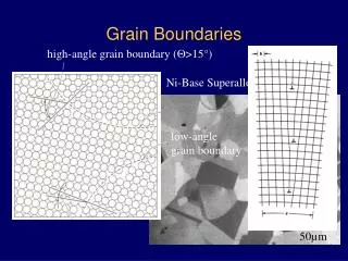
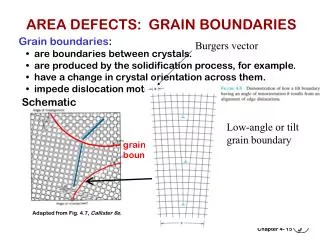
Grain boundaries in ionic conductors The brick layer model S.M. Haile, D.L. West, J. Campbell, Journal of Materials Research 13 (1998) 1576 NorFERM-2008, Gol
Grain boundaries in ionic conductors • The ratio R2 to R1 is dependant on both physical and microstructural properties NorFERM-2008, Gol
Grain boundaries in ionic conductors Criteria for two distinguishable arcs: • R1 and R2 are comparable in magnitude • The characteristic frequencies of the two arcs are significantly different w0 = (re)-1 Assuming ebulk = egb leads to NorFERM-2008, Gol
Grain boundaries in ionic conductors • Assuming a sample with ”normal” microstructure (G >> g) • In the case of two semi-circles: sbulk > sgb • Transport in grains is preferred, but the perpendicular grain boundaries are unavoidable NorFERM-2008, Gol
Grain boundaries in ionic conductors • In the case of only one semi-circle: • The resistance associated with this arc may correspond to the bulk, the parallel grain boundaries or a combination NorFERM-2008, Gol
Grain boundaries in ionic conductors C1~ Cbulk R1 ~ Rgb|| Transport will be preferred along parallel grain boundaries compared to that through grain interiors NorFERM-2008, Gol
Grain boundaries in ionic conductors C1~ Cbulk R1 ~ Rbulk NorFERM-2008, Gol
Grain boundaries in ionic conductors Summary: • Two arcs are observed sbulk > sgb Then sbulk = s1 and sgb~s2C1/C2 • One arc is observed The resistance associated with this arc may correspond to the bulk, the parallel grain boundaries or a combination NorFERM-2008, Gol
Electrodics • The capacitances associated to the electrode processes are much higher than those of bulk and grain boundaries • In order to investigate electrodes, one should apply “small” amplitudes of the probe signal • For bulk and gb: typically 0.1 - 2 V • For electrodes: typically tens of mV • It is also possible to study electrode responses under DC bias NorFERM-2008, Gol
Possible electrode procesess • Charge transfer • Presuambaly happening on the triple phase boundaries • Dissociative adsorption of H2 and/or O2 • Gas diffusion impedance • Gas conversion impedance / gas concentration impedance NorFERM-2008, Gol
Finite length diffusion elements Finite space Warburg element (open terminus) Finite length Warburg element (Short terminus) Warburg element: CPE with n =0.5 NorFERM-2008, Gol
Electrodics: a case study of a complete fuel cell A large number of different contributions (many parameters to fit) Some constraints must be given to fit the data to the model R. Barfod, Fuel Cells 6 (2006) 141. NorFERM-2008, Gol
Limitations of impedance spectroscopy • Many parameters to fit: sufficient amount of data is necessary • Overlapping processes in the frequency-plane may not be separated • In theory, an indefinite number of equivalent circuits can be used to explain a recorded spectrum NorFERM-2008, Gol
Literature and acknowledgments The impedance course at Risø is acknowledged for inspiration R. Barfod, A. Hagen, S. Ramousse, P.V. Hendriksen, M. Mogensen, Fuel Cells 6 (2006) 141. S.M. Haile, D.L. West, J. Campbell, Journal of Materials Research 13 (1998) 1576 NorFERM-2008, Gol
Quiz • In this room at 19:00 • Interesting bonus question!!! NorFERM-2008, Gol