Download
1 / 20
200 likes | 302 Views
Explore the innovative methods used to measure air speed and flow boundary layer thickness on HIAPER's fuselage, crucial for optimizing air sampling. Follow our journey from design to results, showcasing the impact on research and aircraft operations. ####

E N D
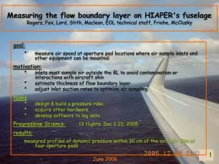
Measuring the flow boundary layer on HIAPER's fuselageRogers, Fox, Lord, Stith, Maclean, EOL technical staff, Friehe, McClusky • goal: • measure air speed at aperture pad locations where air sample inlets and other equipment can be mounted • motivation: • inlets must sample air outside the BL to avoid contamination or interactions with aircraft skin • estimate thickness of flow boundary layer • adjust inlet suction rates to optimize air sampling • tasks • design & build a pressure rake • acquire other hardware • develop software to log data • Progressive Science:13 flights, Dec 1-22, 2005 • results: measured profiles of dynamic pressure within 30 cm of the aircraft skin at four aperture pads June 2006
aperture pads on G-5 related measurements
true air speed ~ (Δp)1/2 • Bernoulli’s equation: p = p0 + ½ x density x velocity2 • RAF Bulletin No. 23, Measurement Techniques: Air Motion Sensing, http://www.atd.ucar.edu/raf/Bulletins/bulletin23.html
velocity profile • law of the wall logarithmic velocity profile within inertial sublayer U / u* = (1/к) ln y+ + const where u* = friction velocity, y+ = scale height к = von Karmen’s constant
pressure rake & scanner ∆p = 16 channels ethernet 50 Hz
flight test maneuvers • speeds & altitudes • normal operating range
dynamic pressure profiles- speed runs - • “boundary layer depth” • distance from skin where speed = 99% of local asymptotic velocity, (or 98% of asymptotic dynamic pressure) • not necessarily the “freestream” value, which is further away from the aircraft.
dynamic pressure profiles- different aperture pad locations -
pitch, side-slip & speed run maneuvers- rake at belly 250-R -
next • Univ. California Irvine studies (Friehe, McClusky) • GAC interest in collaborative study of G-V fuselage BL • acoustics, cabin noise • CFD flow modeling & compare vs rake data • ProgSci project web site • http://www.atd.ucar.edu/raf/Projects/ProgSci/ • more about pressure rake • http://www.atd.ucar.edu/~dcrogers/ProgSci/PressureRake/
speed & AOA- envelope of flight conditions - color = flight i.d. dot = 1 sec of flight