Download
1 / 20
220 likes | 307 Views
The Role of Simulation in Photovoltaics: From Solar Cells To Arrays. Ricardo Borges, Kurt Mueller, and Nelson Braga Synopsys, Inc. PV System Challenges. Improving PV efficiency Optimizing for design performance and target reliability Reducing the effects of variation on system performance

E N D
The Role of Simulation in Photovoltaics: From Solar Cells To Arrays Ricardo Borges, Kurt Mueller, and Nelson Braga Synopsys, Inc.
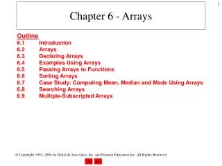
PV System Challenges • Improving PV efficiency • Optimizing for design performance and target reliability • Reducing the effects of variation on system performance • Predicting manufacturing yields • Lowering production costs
Addressing Issues at All Stages Cell Module System Synopsys Saber tools Synopsys TCAD tools • Design criteria – Cell Level • Maximize efficiency • Optimize geometric and process parameters • Design criteria – Module Level • Minimize effect of interconnects on performance • Minimize impact of cell variation or degradation on module performance • Design Criteria – System Level • Maximize system performance accounting for diurnal solar inclination and tracking of solar path (some systems have 1- or 2-axis tracking of the sun) • Maximize system level efficiency delivered to the grid, including inverter system
Process Simulation Device Simulation Current in Drift-Diffusion Model PDE for Pair Diffusion Potential distribution in flash memory LDMOS: doping, mesh 1D doping profile simulation Inductance Simulation PVD (Physical Vapor Deposition) Snapback of a UMOS Photogeneration in CIS Full Chip H-Bridge EM Wave AlGaAs VCSEL Mechanical stress in intermetal dielectric What is TCAD?
Why Simulate Solar Cells? New generation cell (Eff ~ 20%) Early generation cell (Eff ~ 15-16%) Source: SERIS • Continuous innovation makes cells more complex • More process and geometrical variables • 3D effects, complex light path, etc … • It’s impractical to design new cells without simulation • Too many experiments are needed to investigate design space • Risks missing optimum design and market window
Dark & Light I-V IQE, EQE Electrical Data: SRH, Auger, BGN, Mobility Process Simulation Electrical Simulation Device Geometry (doping profiles) Device Geometry Optical generation External reflection Solar Cell Simulation Flow Input Simulation Output Process Flow Recipe Optical Simulation Optical Data: n & k Device Geometry (lifetime, doping profiles)
Example: 2D Cell Optimization • Select parameters to be investigated • Parameterize the TCAD model • Run simulations • Visualize the influence of each parameter Wfront Sf dlfsf Nlfsf Nbulk dsub tbulk Sb Nlbsf dbsf dlbsf wback wtot
Example: Unit Cell Optimization Results wfront wback wtot dsub Nbulk dbsf Nlbsf dlbsf Nlfsf dlfsf tbulk Sf Sb eff FF Voc jsc • Each array of points represents a separate simulated condition • Unit cell pitch, base layer thickness, doping, and lifetime, and surface recombination velocity show major influence on cell response • Design trade-offs can be investigated quantitatively
Application: Back-contact Silicon Cells • Design problem: optimization of metal finger pitch to achieve good performance with low cost screen printing manufacturing • Simulation correctly captures the measured behavior across a range of contact pitch and bulk resistivity • Optimization of the structure results in 21.3% efficiency Source: F. Granek et al, Progress in Photovoltaics: Research and Applications, 17, Oct 2008, pp 47-56 Antireflection Coating (ARC) Surface Texturing n+ FSF Base (n-type) Passivation Metal Contacts n+ BSF p+ emitter Pitch
Application: Multi-Junction Solar Cells • GaAs/GaInP Dual-Junction Cell • Excellent match between Sentaurus simulation and measurements in MJ cells • Calibrated model allows researchers to explore more advanced structures: Bragg reflectors, additional junctions, etc Source: Philipps, S.S. et.al.. NUMERICAL SIMULATION AND MODELING OF III-V MULTI-JUNCTION SOLAR CELLS Proceedings of 23rd EUPVSEC, 2008
Cells to Systems: Why simulate? • Cells alone are physically interesting; • Modules and Systems bring the power of the sun to the end user • Once cell behavior is understood, need model capable of system-level simulation to: • Minimize interconnect losses • Evaluate effects of environmental variation: • Light intensity and incidence angle • Temperature variation • Electrical environment • Optimize power conversion
What is Saber? Multi-domain circuit simulation… enabling full system “Virtual Prototyping” Power Electronics Multiple Domains Behavioral Models Control Algorithms Optimizing System Performance and Reliability Nominal Design Parameter Variation Production Tolerances Statistical Analyses Fault Analyses Worst-Case
Cells to Modules • Design problem: active width optimization • Given TCAD device design, physical parameters contributing to interconnect resistances can be extracted and a system-level model developed
Module Optimization Module Optimization: Variation of equivalent RSeries & RShunt • From system cell level model, sweeps can be done to determine the effect of different cell widths on module performance • Allows for optimization of Maximum Power Point at a module level as a function of luminance and cell width V V IModule (A)
Module Validation • Accurate, physics-based models take TCAD results to system simulation for validating real-world measurements
Modules to Arrays and Systems Photovoltaic Module Performance Verification at Different Cell Temperatures Measurement of MPPT at Different Temperatures • Design problem: Thermal Effects on Module/Array performance and Maximum Power Point • Analysis of faults on strings within the array
System Integration & Optimization • Simulation provides integrated test, validation and optimization environment for all aspects of the system: Environment Power Electronics Control System & Algorithms
Battery Charging System Simulation • System highlights: • Maximum Power Point Tracking through impedance matching using controlled DC/DC converter • Dynamic thermal capable array model
Unit Cells to Systems Simulation • Early validation of novel cell design • Development of application-optimized cells, modules and arrays • System level virtual prototyping for test & validation before anything physical is built