Download
1 / 1
10 likes | 96 Views
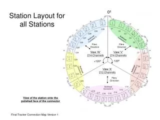
Detailed guide displaying the spatial arrangement of bulkhead connectors, fiber directions, and tracker connections in a structured manner for easy reference. Ideal for optimizing station organization.

E N D
Station Layout for all Stations 0º 20 20 22 22 1 To 20 621 To 640 22 21 To 42 599 To 620 22 43 To 64 C1 577 To 598 C30 22 22 C29 C2 65 To 86 555 To 576 C28 C3 22 22 22 Bulkhead Connector 5 Bulkhead Connector 1 C27 C4 533 To 554 87 To 108 C26 C5 Fibre Direction Fibre Direction 513 To 532 109 To 128 20 20 C25 C6 20 493 To 512 20 129 To 148 View ‘W’ 214 Channels View ‘V’ 214 Channels C24 C7 471 To 492 149 To 170 22 22 C8 C23 -120º +120º C22 449 To 470 C9 171 To 192 22 Bulkhead Connector 2 22 View ‘X’ 212 Channels Bulkhead Connector 4 C10 C21 427 To 448 193 To 214 Fibre Direction 22 22 C11 C20 405 To 426 215 To 236 C12 Bulkhead Connector 3 22 C19 22 C13 385 To 404 237 To 256 C18 C14 C17 C15 C16 365 To 384 257 To 276 20 20 343 To 364 View of the station onto the polished face of the connector 277 To 298 321 To 342 299 To 320 20 20 22 22 22 22 1 Final Tracker Connection Map Version 1