Download
1 / 34
360 likes | 1.1k Views
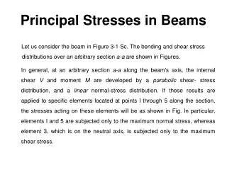
11. In SITU STRESSES. INTRODUCTION. We Will Consider this in the Next Chapter. INTRODUCTION. Soils are multiphase systems. They consists of solid particles enclosing continuous voids which contain water and/or air. Air. Solid. Solid.

E N D
INTRODUCTION We Will Consider this in the Next Chapter
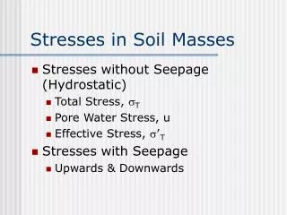
INTRODUCTION • Soils are multiphase systems. They consists of solid particles enclosing continuous voids which contain water and/or air. Air Solid Solid • When an external load is applied to soil it will be carried jointly by the three systems, solid, water, air.
However, it is difficult, if not impossible to analyze such multiphase system. • When the soil is fully saturated, then only water is presented in the voids and the problem becomes relativelysimple. • When an external load is applied to saturated soil it will be carried jointly by the two systems, solid grains and water in the pores. F • The increase in pressure within the pore water causes drainage (flow out of the soil), and the load is transferred to the solid grains. The rate of drainage depends on the permeability of the soil.
If by any mean we can find the part of the load carried by the water for a given external load, then we can find the part carried by the solids. • This is the theme of the Principle of Effective Stress. In other word the principle of effective stress determines the effect of a pore pressure on the behavior of a soil with a given TOTALSTRESS. • It is probably the single most important concept in soil mechanics and geotechnical engineering. • The compressibility and shearing resistance of a soil depend to a great extent on the effective stress.
The concept of effective stress is significant in solving geotechnical engineering problems, such as: • Bearing capacity and settlement of foundations • Lateral earth pressure on retaining structures • Stability of earth slopes
THE PRINCIPLE OF EFFECTIVE STRESS (P.E.S.) • This principle was based on some experimental data with some intuition. It states that: Where • Eq. 1 is more of a working hypothesis than being a physicallaw. • Actually Terzaghi (1925, 1936) arrived at Eq. 1 from the results of laboratory experiments. • Many attempts have been exercised in examining the validity of the concept but no one is conclusive.
Important Remarks (Facts) about P.E.S. • The behavior of soils is solely controlled by the value of , therefore in engineering is what matter because all measurable effects of a change of stress, such as: • COMPRESSIBILITY • DISTRORION • SHEAR STRENGTH are exclusively due to changes in the effective stress. • If there are two soils with the same structure and mineralogy, there behavior will be the same if they are subjected to the same effective stress. (The following example will demonstrate this). • Cannot be measured, it can only be calculated.
Example 104 m 1 m 1 m • Consider two sediments of the same soil, (a) an estuarine sediment and (b) a deep-sea sediment. The unit weight is 17 kN/m3. Calculate the vertical effective stress: (b) (a) • The two sediments have the same value of effective stress. Hence if they have the same structure and mineralogy, they will have the same engineeringproperties.
F Theoretical Basis for the Effective Stress Principle Area A = Total Area As = Area of solid Aw = Area of water Aa = Area of air Force F = Total applied force Fs = Portion of force carried by solid Fw = Portion of force carried by water Fa = Portion of force carried by air
Substituting Eq. (5) into Eq. (4) Refer to Eq. 2 Substituting Eq. (7) into Eq. (6) yields • The term aspsis called intergranular stress. It is not precisely equal to the effective stress. • Sometimes, in granular material effective stress is taken to be equal to the intergranular stress. • However, this is not true, because the grain-to-grain contact area may be very small and intergranular stress will be extremely high and hence greater than the effective stress.
Taking asps to be effective stress we have For dry soil u = 0, and • Instead of pw we use u as it is conventional in soil mechanics. • Effective stress is approximately the force per unit area carried by soil skeleton.
EVALUATION OF EFFECTIVE STRESS • We now know the importance of effective stress and that it is responsible for soil behavior and the dilemma that we cannot measure it. • However, as can be seen in Eq. 1, if we can find and u, then • Therefore, our job now is to find and u. I. Determination of total stress, a. No external load is applied Where g = Unit weight of the soil, the unit weight of the soil may be, wet, saturated, dry. (This depends on the degree of saturation of soil).
z = The vertical distance from the surface to the point at which is evaluated. in Eq. 14 is called the BODY STRESS because it is generated by the mass located upon by gravity in the body. Also it is usually refereed to as OVERBURDEN. b. If an external load is applied In this case the total stress at depth z is given by Where is the stress due to the external load at depth z excluding the weight of soil i.e. z. We will discuss in the following chapter different ways for evaluating .
II. Determination of p.w.p, u a. No external load is applied Where w= Unit weight of water Therefore, by substituting Eq. 15 and Eq.16 into Eq.14, we get b. No external load is applied, but there is steady state seepage From Bernoulli's equation We find h from Laplace’s equation We use the flownet
c. External load is applied This will be covered in Geotechnical Engineering II such that: i. Fully Undrained Condition We find Skempton’sp.w.p parameters A and B in the laboratory and to use them in evaluating u in the field. A and B are discussed in Geotechnical Engineering II. ii. Consolidation Condition If we have partially drained condition in (Transient flow). Then it is the Theory of Consolidation which enables us to keep trace of u and hence . This theory will be discussed in details in Geotechnical Engineering II. As can be seen case (a) is very simple and (c)is treated in CE 481. Since by now we have a background in seepage, we will next discuss case (b).
1. Stresses in Saturated Soil in the Static Case • The rate of water supply is kept constant. • At point A, • Total Stress: sA= H1 gw • Pore water pressure: uA = H1 gw • Effective stress:s’A= 0 • At point B, • Total Stress: sB= H1 gw + H2 gsat • Pore water pressure: uB = (H1 + H2) gw • Effective stress:s’B= H2(gsat – gw) = H2g’ at Point A at Point C • At point C, • Total Stress: sC= H1 gw + zgsat • Pore water pressure: uC = (H1 + z) gw • Effective stress:s’C= z(gsat – gw) = z g’ at Point B
Example 1 Calculate the total, neutral, and effective stresses at elevation A when: • The water table is at elevation A. • The water table rises to elevation B. The saturated unit weight is 19.62 kN/m3 Solution a. b.
Example 2 Plot the variation of total, effective vertical stresses, and pore water pressure with depth for the soil profile shown below.
Solution Within a soil layer, the unit weight is constant, and therefore the stresses vary linearly. Therefore, it is adequate if we compute the values at the layerinterfaces and watertablelocation, and join them by straight lines.
Example 3 Plot the variation of total and effective vertical stresses, and pore water pressure with depth for the soil profile shown below.
2. Stresses in Saturated Soil with Upward Seepage • In case of seepage the effective stress at any point in a soil mass will differ from that in the static case. Note: For illustration we consider simple 1D case z • Therefore the effective stress decreases when there is upward seepage. It decreases by exactly the increase in p.w.p.
Quick Condition (Boiling) • For the case of upward seepage, what happen if the hydraulic gradient gradually increased. At a certain value of hydraulic gradient the effective stress will be zero (Note that cannot be less than zero). • ic is called the CRITICAL HYDRAULIC GRADIENT. It is the value of I when a quick condition occurs. • Recall that Note: fully saturated soil
Remarks • The approach we just used to obtain icis based on the premise that quick conditionsoccur when at theBOTTOM of the soil column is zero. • Each point of the soil column has its own ic. However ic for the point at the bottom will be the first one to occur since it has the largest gradient all times. • For most soils 0.9 < ic < 1.1 with an average of 1.0.
3. Stresses in Saturated Soil with Downward Seepage • At A, • Total Stress: sA= H1 gw • Pore water pressure: uA = H1 gw • Effective stress:s’A= sA - uA = 0 • At B, • Total Stress: sB= H1 gw + H2 gsat • Pore water pressure: uB = (H1 + H2 - h) gw • Effective stress:s’B= H2(gsat – gw) + h gw • At C, • Total Stress: sC= H1 gw + zgsat • Pore water pressure: uC = (H1 + z– h/H2 z) gw • = (H1 + z– i z) gw • Effective stress:s’C= z(gsat – gw) + izgw • = zg’ + izgw
s’C= z g’ Static Case s’C Upward Seepage Downward Seepage
Example 4 A section through a dam is shown across. Determine: • The p.w.p. at points 1,3, and 4 • The effective stress at point 2 if the saturated unit weight for the soil is 18kN/m3. h = 6.3 m , Nd = 10, h =6.3/10 = 0.63 m 1.6 Datum 6.3 9.4 17.2 B. A.
Example 5 A section through a sheet-pile wall which we have considered in the previous chapter is shown below. Determine:- • The effective stress at points (a and b) if the soil has a unit weight of 18 kN/m3. • What depth of water behind the sheet-pile wall (i.e. above the upstream ground surface) will cause a quick condition at point (a). Datum
Solution: H = 11 m, Nd = 8 , h =11/8 = 1.375 m A. Point (a) Datum B. Point (b) For quick condition at point (a) we have
SEEPAGE FORCE • We have seen in the preceding sections that the effective stress at a point in a soil layer would increase or decrease due to seepage. • For the static case the effective stress at depth z measured from the surface of the soil layer is given by • Therefore, the effective force on an area A is • If there is an upward seepage of water in the vertical direction through the same soil layer, the effective force on an area A at a depth z is given by,
Hence, the decrease in the total force because of seepage is • It is often convenient to express the seepage force per unit volume. Hence the seepage force per unit volume of soil is Remarks • Flow nets can be used to find iat any point and, thus, seepage force per unit volume of soil. This is important in analyzing the stability of structures where heave is of a problem. • In an isotropic soils, the force acts in the samedirection as the direction of flow.
SEEPAGE FORCE Static (Hydrostatic) s’C= z g’ s’C Upward Seepage Downward Seepage