Download
1 / 53
730 likes | 1.31k Views
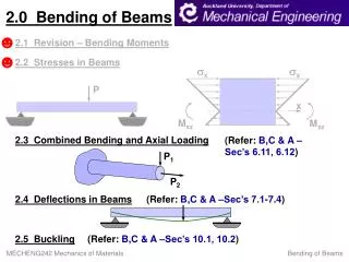
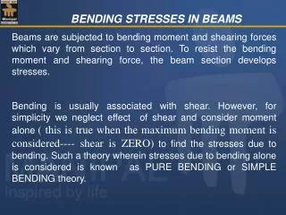
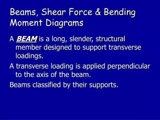
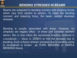
BENDING STRESSES IN BEAMS. Beams are subjected to bending moment and shearing forces which vary from section to section. To resist the bending moment and shearing force, the beam section develops stresses.

E N D
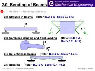
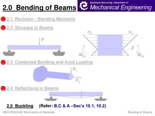
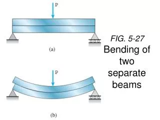
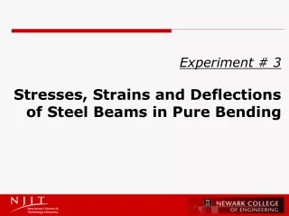
BENDING STRESSES IN BEAMS Beams are subjected to bending moment and shearing forces which vary from section to section. To resist the bending moment and shearing force, the beam section develops stresses. Bending is usually associated with shear. However, for simplicity we neglect effect of shear and consider moment alone ( this is true when the maximum bending moment is considered---- shear is ZERO) to find the stresses due to bending. Such a theory wherein stresses due to bending alone is considered is known as PURE BENDING or SIMPLE BENDING theory.
C D B A a a VB= W VA= W SFD + - Example of pure bending W W Wa Wa Pure bending between C & D + BMD
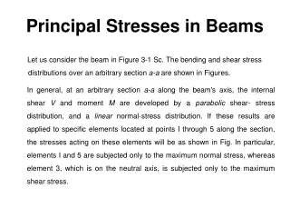
σc Neutral Axis σt BENDING ACTION:
Neutral layer σt Neutral Axis σc
BENDING ACTION • Sagging-> Fibres below the neutral axis (NA) get stretched -> Fibres are under tension • Fibres above the NA get compressed -> Fibres are in compression • Hogging-> Vice-versa • In between there is a fibre or layer which neither undergoes tension nor compression. This layer is called Neutral Layer (stresses are zero). • The trace of this layer on the c/s is called the Neutral Axis.
Assumptions made in Pure bending theory • The beam is initially straight and every layer is free to expand or contract. • The material is homogenous and isotropic. • Young’s modulus (E) is same in both tension and compression. • Stresses are within the elastic limit. • The radius of curvature of the beam is very large in comparison to the depth of the beam.
6) A transverse section of the beam which is plane before bending will remain plane even after bending. 7) Stress is purely longitudinal.
BS 7 Note: homogeneous: of the same kind throughout Isotropic: of equal elastic properties in all directions. w1 Longitudinal axis A transverse section of the beam = the cross section of the beam
DERIVATION OF PURE BENDING EQUATION PART I: Relationship between bending stress and radius of curvature.
Consider the beam section of length “dx” subjected to pure bending. After bending the fibre AB is shortened in length, whereas the fibre CD is increased in length. In b/w there is a fibre (EF) which is neither shortened in length nor increased in length (Neutral Layer). Let the radius of the fibre E'F′ be R . Let us select one more fibre GH at a distance of ‘y’ from the fibre EF as shown in the fig. EF= E'F′ = dx = R dθ The initial length of fibre GH equalsR dθ After bending the new length of GH equals G'H′= (R+y) dθ = R dθ + y dθ
Change in length of fibre GH = (R dθ + y dθ) - R dθ = y dθ Therefore the strain in fibre GH Є= change in length / original length= y dθ/ R dθ Є = y/R If σь is the bending stress and E is the Young’s modulus of the material, then strain Є = σь/E σь/E = y/R => σь = (E/R) y---------(1) σь= (E/R) y => i.e. bending stress in any fibre is proportional to the distance of the fibre (y) from the neutral axis and hence maximum bending stress occurs at the farthest fibre from the neutral axis.
σc A N σt Note: Neutral axis coincides with the horizontal centroidal axis of the cross section
σc Neutral Axis σt Moment of resistance on one side of the neutral axis there are compressive stresses and on the other there are tensile stresses. These stresses form a couple, whose moment must be equal to the external moment M. The moment of this couple, which resists the external bending moment, is known as moment of resistance.
da y A N Moment of resistance Consider an elemental area ‘da’ at a distance ‘y’ from the neutral axis. The force on this elemental area = σь × da = (E/R) y × da {from (1)} The moment of this resisting force about neutral axis = (E/R) y da × y = (E/R) y² da
Total moment of resistance offered by the beam section, • M'= (E/R) y² da • = E/R y² da • y² da =second moment of the area =moment of inertia about the neutral axis. • M'= (E/R) INA For equilibrium moment of resistance (M') should be equal to applied moment M i.e. M' = M Hence. We get M = (E/R) INA
(E/R) = (M/INA)--------(2) From equation 1 & 2, (M/INA)= (E/R) = (σь/y) ---- BENDING EQUATION. (Bernoulli-Euler bending equation) Where E= Young’s modulus, R= Radius of curvature, M= Bending moment at the section, INA= Moment of inertia about neutral axis, σь= Bending stress y = distance of the fibre from the neutral axis
SECTION MODULUS: (M/I)=(σь/y) or σь = (M/I) y Its shows maximum bending stress occurs at the greatest distance from the neutral axis. Let ymax = distance of the extreme fibre from the N.A. σь(max) = maximum bending stress at distance ymax σь(max) = (M/I) y max where M is the maximum moment carrying capacity of the section, M = σь(max) (I /y max) M = σь(max) (I/ymax) = σь(max)Z Where Z= I/ymax= section modulus (property of the section) Unit ----- mm3 , m3
N A Y max=d/2 section modulus (1) Rectangular cross section b Z= INA/ ymax =( bd3/12) / d/2 =bd2/6 d
B b D/2 d/2 D N A Ymax=D/2 d Y max=d/2 A N (2) Hollow rectangular section Z= INA / ymax =1/12(BD3-bd3) / (D/2) =(BD3-bd3) / 6D (3) Circular section Z= INA / ymax =(d4/64) / (d/2) = d3/ 32
Y max = 2h/3 h N A b (4) Triangular section Z = INA / Y max =(bh3 /36) / (2h/3) =bh2/24 h/3
200 mm w / unit run 300 mm 5 m NUMERICAL PROBLEMS (1) Calculate the maximum UDL the beam shown in Fig. can carry if the bending stress at failure is 50 MPa & factor of safety to be given is 5. Maximum stress = 50 N/mm² Allowable (permissible) stress = 50/5 =10 N/mm2
σbmax Ymax External Bending moment Moment of resistance or moment carrying capacity of the beam = M' External maximum Bending moment Maximum Moment of resistance or maximum moment carrying capacity of the beam = M' σb will be maximum when y = ymax and M = Mmax
We have to consider section of the beam where the BM is max, and stress should be calculated at the farthest fibre from the neutral axis. E/R=M/INA= σb/y M/INA= σb/y => INA = bd³/12= (200× 300³)/12= 45 ×107 mm4 Ymax= d/2=300/2= 150 mm BMmax =wl²/8= w ×(5000) ²/8 (w ×5000²/8) / 45 ×107 = 10/150 w= 9.6 N/mm = 9.6 kN/m
(2) For the beam shown in Fig. design a rectangular section making the depth twice the width. Max permissible bending stress = 8 N/mm² .Also calculate the stress values at a depth of 50mm from the top & bottom at the section of maximum BM. 9 KN 12 KN/m b A B 2.5 m 3.5 m d=2b
MA=0 (12×6 ×3) + (9 ×2.5) -VB×6 = 0 VB= 238.5/6 =39.75 kN ΣFy = 0 VA + VB=(12 ×6)+ 9 VA= 41.25 kN
11.25 kN 41.25 kN + 2.25 kN - 39.75 kN 9 KN 12 KN/m A B C 2.5 m 3.5 m Max. bending moment will occur at the section where the shear force is zero. The SFD shows that the section having zero shear force is available in the portion BC. Let that section be X-X, considered at a distance x from support B as shown below. The shear force at that section can be calculated as
X x X 12 KN/m A B 2.5 m 3.5 m -VB+12 x =0 i.e. -39.75+12x=0 x = 39.75/12 =3.312 m. BM is max @ 3.312m from B. BM@xx = 39.75×3.31 - 12×3.31×(3.31)/2 = 65.84 kN-m = 65.84× 10 6 N mm
Now M/I NA= σb/y 65.84×10⁶/(b×(2b)3/12) = 8/b b³= 1.5×8.23×106 b= 231.11 mm , d= 2b= 462.22 mm
8 N/mm2 σc 50 mm σt 50 mm 8 N/mm2 231.11mm 231.11 462.22mm N A 231.11 From similar triangles, 8/ 231.11 = σc/(231.11-50) = σt / (231.11-50) σc = 6.27 N/ mm2( compressive) & σt = 6.27 N/ mm2(tensile)
(3)A Rolled Steel Joist (RSJ) of 200mm × 450 mm of 4m span is simply supported on its ends. The flanges are strengthened by two 300mm× 20mm plates one riveted to each flange. The second moment of the area of the RSJ equals 35060×104 mm4. Calculate the load the beam can carry for the following cases, if the bending stress in the plates is not to exceed 120 MPa, (a) greatest central concentrated load (b) maximum UDL throughout the span 300 20 450 4m RSJ 20 200
300 20 450 20 200 INA=I NA(RSJ)+MI due to plates about NA = (35060 ×104 )+2 [(300 ×(20)³/12+300 ×20 ×(235)²] =1.01 × 109 mm4 245 mm N A 245 mm
(a) M/INA= σb/Y [Mmax=PL/4] Ymax = (450+2 ×20) /2= 245mm σ=120N/mm2 (P ×4000) / 4 (1.01 ×10⁹)=120/245 P = 4.95×10⁵ N (b) M/INA= σb/Y [Mmax= wl2/8] Ymax = (450+2 ×20) /2= 245mm w = 247.35 N/ mm = 247.35 KN/m
(4) An I section beam has 200 mm wide flanges and an overall depth of 500 mm. Each flange is 25 mm thick and the web is 20 mm thick. At a certain section the BM is ‘M.’ Find what percentage of M is resisted by flanges and the web. 200 25 20 500
σmax 250 The moment of resistance (moment carrying capacity )of the entire section is given by M/INA= σmax/ymax M=( σmax ×INA )/ymax = (σmax ×7.14 × 10⁸) /250 =2.86 × 10⁶ σmax INA=2[(200 × 25³/12)+200×25 ×(237.5)²] +(20×(450)³/12) =7.14 × 108 mm4
σmax σ 250 y Consider an element of thickness dy at a distance of y from neutral axis Let σmax be the extreme fibre stress( maximum bending stress)
From similar triangle principle σmax / σ=250/y σ =( σmax× y) /250 Area of the element =200× dy Force on the element = stress × area P= (σmax×y/250) ×( 200 dy) The moment of resistance of this about the NA equals = (σmax×y/250) ×( 200 dy) y =(4/5) y² σmaxdy
Therefore moment of resistance of top flange = Total moment of resistance of both the flanges =2.26x10⁶ σmax % moment resisted by flanges =(MF/M) × 100 =(2.16 × 10⁶ σmax )/(2.86 × 106 ×σmax) ×100 =79.02% Therefore % moment resisted by the web= 20.98%
OR Total moment of resistance (moment carrying capacity )of both the flanges where INA=2[(200 × 25³/12) +200×25 ×(237.5)²] =5.64 × 108 mm4 M = 2.26×10⁶σmax
X x X (5)Locate & calculate the position and magnitude of maximum bending stress for the beam shown. 500 N 5mm 10mm 80 mm Let us consider a section X-X at a distance of ‘x’ from the free end.
Bending stress is not maximum at left end (10 mm dia end) because at that end bending moment may be maximum but Ixx is also maximum.
Dx/2 Diameter at X-X , Dx =5 + x/16 Dx=5 + 0.0625 x Therefore Ixx= Dx4/64 = (5 + 0.0625x)4 /64 M/I= σb/y Mxx= 500x, y= ymax @ section x-x = Dx/2 σb(x-x) = (Mxx×ymax) / Ixx σb(x-x)= (500 × x × Dx) / (2 × Ixx)
σb(x-x)= (500 × x × Dx )/ (2 × Dx4/64 ) = (5092.96 × x) / Dx3 =(5092.96 x) / (5+0.0625x)3 = (5092.96 x ) (5+ 0.0625x)-3 Now, to have maximum bending stress, dσb(xx) /dx = 0 5+ 0.0625x =0.1875x x = 40 mm Max bending stress = 483.13 Mpa
200mm 25mm 250 mm 25mm (6) The beam section shown in fig. has a simple span of 5 m. If the extreme fibre stresses are restricted to 100 MPa & 50 MPa under tension & compression respectively, calculate the safe UDL (throughout the span) the beam can carry inclusive of self weight. What are the actual extreme fibre stresses?
=ay / a = 200×25 × (250+12.5) + 250 ×25 ×125 (200 ×25) +(250 ×25) = 186.11mm INA= (200 × 253)/12 + 200 × 25 ×(88.89-12.5)2 +(25x2503 )/12 + 25 × 250 ×(186.11-125)2 =85.32x106mm4 200mm 25mm 88.89 mm 186.11 mm 25mm
σc 88.89 mm 186.11 mm Let us allow the permissible value of stress in tension σt=100 N/mm2 From similar triangles σc / σt = 88.89/186.11 σc / 100= 88.89/186.11 σt σc =47.762N/mm2 < 50 Hence safe. The actual extreme fibre stress values are σc = 47.762N/mm2 & σt = 100 N/mm2
Mmax=wl2/8 = w × 50002/8 y=186.11 for σt=100 y=88.89 for σc =47.762 M/INA= σb/y (wl2)/(8 × 85.32 × 106) = 100/186.11= 47.72/ 88.89 w =14.67 N/mm=14.67 KN/m
PRACTICE PROBLEMS BS 1 1) Find the width “x” of the flange of a cast iron beam having the section shown in fig. such that the maximum compressive stress is three times the maximum tensile stress, the member being in pure bending subjected to sagging moment. ( Ans: x= 225 mm)
2)A cast iron beam has a section as shown in fig. Find the position of the neutral axis and the moment of inertia about the neutral axis. When subjected to bending moment the tensile stress at the bottom fibre is 25 N/mm². Find, a) the value of the bending moment b) the stress at the top fibre. ( Ans: M= 25070 Nm, σc =33.39 N/mm²)
BS 3 3)A cast iron beam has a section as shown in fig .The beam is a simply supported on a span of 1.25 meters and is used to carry a downward point load at midspan. Find the magnitude of the load if the maximum tensile stress on the beam section is 30 N/mm². Determine also the maximum compressive stress. (Ans. W= 174.22 N, σc =40.73 N/mm²)
BS 4 4)A groove 40mm×40mm is cut symmetrically throughout the length of the circular brass section as shown in fig. If the tensile stress shall not exceed 25 N/mm², find the safe uniformly distributed load which the brass can carry on a simply supported span of 4 meters. ( Ans: 5150 N/m)