Download
1 / 19
190 likes | 362 Views
Water Availability Modeling in the State of Texas. CE 394 K.2 - Surface Water Hydrology University of Texas at Austin David Mason. Outline. Project Objectives Source Data Collection Analysis of Data Presentation of Results Possible Solutions Conclusions Future Work. Project Objectives.

E N D
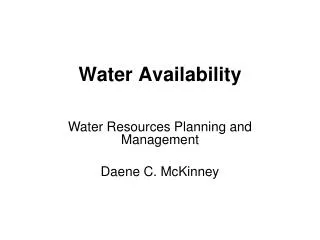
Water Availability Modeling in the State of Texas CE 394 K.2 - Surface Water Hydrology University of Texas at Austin David Mason
Outline • Project Objectives • Source Data Collection • Analysis of Data • Presentation of Results • Possible Solutions • Conclusions • Future Work
Project Objectives • Use GIS utilities to create a spatial water rights database • Compile watershed data for each water right and stream gage location in selected basins • Drainage area, avg. precip, avg. CN, flowlength to outlet • Compare GIS results with established USGS values • Study the effects of using higher resolution DEMs
Selected Basins Guadalupe San Antonio Nueces
Source Data Collection • Digital Elevation Models (USGS) • RF3 Coverages (EPA) • Water Right and Diversion Locations (TNRCC) • Primary Control Points (Relevant Contractor) • Precipitation Grid (Oregon State) • Curve Number Grid (CRWR) • Digital Raster Graphics (TNRIS)
Process the DEMs Guadalupe Nueces San Antonio
Download and Edit RF3 Talk to Brad!
Water Rights and Diversions -The San Antonio Basin had 488 water right locations when it was sent to TNRCC -When I got it back….488 turned into 788!!
Primary Control Points • Primary control points are mainly stream gage locations used to distribute naturalized flows throughout the basin • Control points and locations were provided by HDR • Arc/Info was used to create an Arcview theme of these control points
Precipitation and CN Grid • The precipitation grid received from Oregon State was resampled to the same size as the DEM • Once resampled, a calculation was preformed in Arc/Info to produce a grid of the average precipitation across the basin • The same basic procedure was used to produce the CN grid
Flow Length Grid • The flow length grid is calculated using the Hydrologic extension in Arcview • The extension calculates the distance to an assigned outlet for each cell in the grid
Calculating the Parameters • Once all the grids have been produced, the next step is to place the points on the flow accumulation grid in order to assure the accurate calculation of the parameters • After the points are in place, a script is run that selects the value of each grid cell “under” a point and attributes those values in a table
End Result of a Very Long Process • The result is a coverage with avg. CN, avg. precip., flowlength and # of cells in the flow accumulation grid • The # of cells are then converted to an equivalent drainage area
Results - Nueces The GOOD Average Error in Area = 1.36%
Results - San Antonio The BAD Average Error in Area = 3.44%
Results - Guadalupe The UGLY Average Error in Area = 3.57%
Possible Problems • DEM Resolution • Currently using 90m, just received 30m • Degree of Terrain Relief • Guadalupe is somewhat of a coastal basin • God Forbid! USGS May Be Wrong!! • Numbers based on old maps • No one’s perfect!
Conclusions • GIS can be used effectively to compute watershed parameters for a large number of control points • Although some of the results are somewhat different than USGS values, the new 30m data sets should help to reduce this error
Future Work • Find a way to use the new 30m DEM data sets in an efficient manner • the current file sizes are far too large • Apply some quality control techniques to assure more accurate results • hand-delineate some of the smaller watersheds to make sure the larger ones aren’t masking discrepancies