Download
1 / 80
961 likes | 1.4k Views
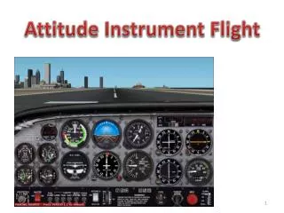
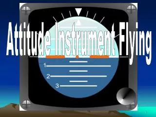
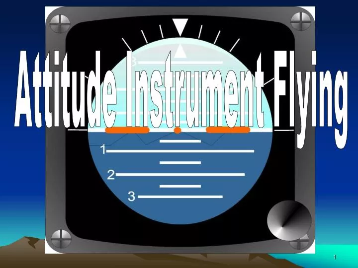
Attitude Instrument Flying. Terminal Learning Objective. Interpret flight instruments indications needed to maintain aircraft attitude during IFR flight. Attitude Instrument Flying. Control of an aircraft’s spatial position by using instruments rather than outside visual references.

E N D
Terminal Learning Objective Interpret flight instruments indications needed to maintain aircraft attitude during IFR flight.
Attitude Instrument Flying • Control of an aircraft’s spatial position by using instruments rather than outside visual references. • Proper instrument interpretation is the basis for helicopter control. • Know how a particular instrument functions so you can translate that information into a control response.
IMC (Flight Instruments) Proper Instrument Interpretation is the Basis for Aircraft Control REQUIRES SKILL !!! Uh-Oh!
Three Fundamental Skills Instrument Interpretation Cross Checking Aircraft Control
Cross Checking Scanning and monitoring two or more instruments to determine the attitude and performance of the aircraft.
Six Basic Flight Instruments • Attitude indicator • Altimeter • Airspeed indicator • HSI • VSI • Turn and Slip
Three Fundamental Skills • Scan: The instruments included in the scan are dependent upon the maneuver performed. • Practice !!!!!
Three Fundamental Skills Cross Check Errors: Fixation: Staring at one instrument too long. Omission: Inadvertently omitting an instrument from the cross check. Emphasis: concentrating too heavily on one or two instruments during the cross check.
INSTRUMENT INTERPRETATION Primary Instruments Supporting Instruments
Basic flight Instruments • Direct indicating instruments Attitude Indicator • Indirect indicating instruments Vertical Speed Indicator Altimeter Airspeed Indicator Heading Indicator Torque meter
Rule #1 CONTROL THE AIRCRAFT
Rule #2 Attitudeof the aircraft Power + Performance =
Control Instruments • Attitude Indicator • Torquemeter Gauge
Performance Instruments Altitude: Altimeter Vertical Speed Indicator Airspeed: Airspeed Indicator Direction: HSI/RMI Turn and Slip
Flight Axis Vertical Axis (Yaw) PITCH The angular relationship of the longitudinal axis to the natural horizon. The aircraft’s attitude rotates around the lateral axis. Longitudinal Axis (Bank / Roll) Lateral Axis (Pitch)
Attitude Indicator Direct indication of aircraft pitch attitude Provides Simultaneous Pitch & Bank indications Supporting instrument for pitch attitude
10° Nose Up/Down 5° Nose Up/Down Horizon Miniature aircraft
PITCH INDICATIONS NOSE LOW
PITCH INDICATIONS HIGH NOSE
Primary pitch attitude instrument. ALTIMETER Indicates height above MSL.. Calibrated to convert atmospheric pressure to an altitude indication
298 299 NOSE LOW DESCENDING
298 299 CLIMBING NOSE HIGH
ACCURACY & RELIABILITY CHECKED PRIOR TO EACH IFR FLIGHT MUST BE WITHIN +/- 70 FEET OF FIELD ELEVATION WHEN SET TO AIRFIELD BAROMETRIC PRESSURE Reference – FM 3-04.240 paragraph 1-10, page 1-4
Set Altimeter to Field Elevation Before Engine Start 298 299
Reads 29.85 in HG 298 299 KOLLSMAN WINDOW
298 298 299 299 Now set 29.90 Altimeter error with Kollsman window set to 29.85” and field altimeter setting from ATIS 29.90. (Rotors turning) 29.90 - 29.85 = 0.05 ( 50 feet error)
Vertical Speed Indicator Supporting Pitch Indicates Climb/Descent in Feet Per Minute *IVSI no lag but affected by turbulence VSI - has 6 - 9 sec lag
Vertical Speed Indicator 500 FPM Climb 500 FPM Descent 1000 FPM Climb
Nose low Descending Nose high Climbing Decelerating Accelerating Airspeed Indicator Supporting Pitch attitude instrument level flight Indirect pitch indicator
Bank Attitude • Angular relationship of the lateral axis to the horizon. • Aircraft rotates around the longitudinal axis. Longitudinal Axis (Bank / Roll)
Primary Bank Instrument Initially Supporting Pitch
RIGHT TURN
NOSE HIGH LEFT TURN
Indirect Indicating Instruments used in Controlling Bank Attitude • Horizontal Situation Indicator (HSI) • Radio Magnetic Indicator (RMI) • Magnetic Compass • Turn and Slip Indicator
RMI HSI Indications in a LEFT turn Primary Bank Instrument
RMI HSI Indications in a Right turn Primary Bank Instrument
Magnetic Compass N 33 30 3 6 Turn Leftto heading 330° Turn Rightto heading 030°.
Types of Turns • Standard rate • Half standard rate • Steep turns
12 - 15 degrees @ 90 KTs = 3°/second RIGHT TURN Standard Rate
12 - 15 degrees @ 90 KTs = 3°/sec LEFT TURN Standard Rate
2 MIN TURN Primary/Supporting Bank Instrument
Characteristics of a Standard Rate Turn • Bank angle 12° to 15° • Turn rate 3° per second • Used for heading changes of 20° or more. 2 MIN TURN
2 MIN TURN Standard Rate
Characteristics of a Half Standard Rate Turn • Bank angle 6° to 71/2° • Turn rate 11/2° per second • Used for heading changes of less than 20°. 2 MIN TURN
2 MIN TURN 1/2 Standard Rate