Download
1 / 58
580 likes | 811 Views
The Crystalline Solid State. Chapter 7. Crystalline Solid State. Many more “molecules” in the solid state. We will focus on crystalline solids composed of atoms or ions. Unit cell – structural component that, when repeated in all directions, results in a macroscopic (observable) crystal.

E N D
The Crystalline Solid State Chapter 7
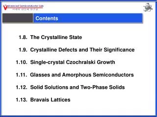
Crystalline Solid State • Many more “molecules” in the solid state. • We will focus on crystalline solids composed of atoms or ions. • Unit cell – structural component that, when repeated in all directions, results in a macroscopic (observable) crystal. • 14 possible crystal structures (Bravais lattices) • Discuss positions of atoms in the unit cell.
The Cubic Unit Cell (or Primitive) • 1 atom per unit cell (how?). • What is the coordination number? Volume occupied? • Let’s calculate the length of the edge. What size of sphere would fit into the hole?
The Body-Centered Cubic • How many atoms per unit cell? • What is the length of the edge? This is a more complicated systems than the simple cubic.
Close-Packed Structures • How many atoms is each atom surrounded by in the same plane? • What is the coordination number? • Hexagonal close packing (hcp) – discuss the third layer (ABA). • Cubic close packing (ccp) or face-centered cubic (fcc) – discuss the third layer (ABC). • Two tetrahedral holes and one octahedral hole per atom. Can you see them?
Close-Packed Structures • The hcp has hexagonal prisms sharing vertical faces (Figure). • How many atoms per unit cell in the hcp structure? • What is the length of the cell edge? • The unit cell for the ccp or fcc is harder to see. • Need four close-packed layers to complete the cube. • What is the length of the cell edge? • In both close-packed structures, 74.1% of the total volume is occupied.
Ionic Crystals • The tetrahedral and octahedral holes can have varying occupancies. • Holes are generally filled by smaller ions. • Tetrahedral holes • Octahedral holes • NaCl structure
Metallic Crystals • Most crystalize in bcc, ccp, and hcp structures. • Hard sphere model does not work well. • Depends on electronic structure. • Properties • Conductivity • Dislocations
Diamond • Each carbon atom is bonded tetrahedrally to four nearest neighbors (Figure). • Essentially the same strength in all directions.
Structures of Binary Compounds • Close-packed structures are generally defined by the larger ions (usually anions). The oppositely-charged ions occupy the holes. • Two important factors in considering the structure • Radius ratio (r+/r-) • Relative number of combining cations and anions.
NaCl Crystal Structure • Face-centered cubes of both ions offset by a half a unit cell in one direction. • Many alkali metals have this same geometry. • What is the coordination number (nearest neighbor)?
CsCl Crystal Structure • Chloride ions form simple cubes with cesium ions in the center (Figure 7-7). • The cesium ion is able to fit in to center hole. How? • Other crystal structures.
TiO2 (the rutile structure) • Distorted TiO6 octahedra. • Ti has a C.N. of 6, octahedral coordination • O has a C.N. of 3
Rationalization of Structure of Crystalline Solids • Predicting coordination number from radius ratio (r+/r-). • A hard sphere treatment of the ions. • Treats bonding as purely ionic. • Simply, as as the M+ ratio increases, more anions can pack around it. • Table 7-1. Let’s look at a few (NaCl, CaF2, and CaCl2).
Thermodynamics of Ionic Crystal Formation • A compound tends to adopt the crystal structure corresponding to lowest Gibbs energy. M+(g) + X-(g) MX(s) G = H - TS (standard state), 2nd term can be ignored • Lattice enthalpy MX(s) M+(g) + X-(g) HL (standard molar enthalpy change) Currently, we are interested in lattice formation.
The Born-Haber Cycle • A special thermodynamic cycle that includes lattice formation as one step. • The cycle has to sum up to zero if written appropriately. • Write down values for KCl.
The Born-Haber Cycle • Calculate the lattice enthalpy for MgBr2. • A discrepancy between this value and the real value may indicate the degree of covalent character. • We have assumed Coulombic interactions between ions. • The actual values for KCl and MgBr2 are 701 and 2406 kJ/mol (versus 720 and 2451).
Lattice Enthalpy Calculations • Considering only Coulombic contributions • The electrostatic potential energy between each pair. zA, zB = ionic charges in electron units r0 = distance between ion centers e = electronic charge 4o = permittivity of a vacuum e2/ 4o = 2.307 10-28 J m Calculation would be performed on each cation/anion pair (nearest neighbor).
Lattice Enthalpy Calculations • A more accurate equation depicts the Coulombic interactions over the entire crystal. NA = Avogadro’s constant A = Madelung’s constant, value specific to a crystal type (in table). This is a sum of all the geometric factors carried out until the interaction become infinitesimal.
Lattice Enthalpy Calculations • Repulsions between ions in close proximity term. C’ = constant (will cancel out when finding the minimum) • = compressibility constant, ~ 30 pm • Combining terms
Lattice Enthalpy Calculations • Finding the minimum energy • dU/dr0 = O • A negative of this value may be defined as the lattice enthalpy.
Lattice Enthalpy Calculations • As the polarizability of the resultant ions increase the agreement with this ionic model worsens. • Polarizibility generally indicates more covalent character. Calculations NaCl and CaBr2
Molecular Orbitals in Solids • A very large number of atoms are used to generate molecular orbitals. • One-dimensional model. • Creation of bands that are closely spaced. • Factors affecting the width of the band. This would be called an ‘s band’. A similar model can be constructed for the p-orbitals and d-orbitals.
Molecular Orbitals in Solids • Band gap – separation between bands in which no MOs exist (Figure 7-13). • Valence band – highest energy band containing electrons. • Conduction band – the band immediately above the valence band in energy.
Metals and Insulators • Metals • Partially filled valence band (e.g. s band) • Electrons move to slightly higher energy levels by applying a small voltage. Electrons and ‘holes’ are both free to move in the metal. • Overlapping bands (e.g. s and p bands) • If the bands are close enough in energy (or overlapping) an applied voltage can cause the electrons to jump into the next band (conduction band).
Density of States • Concentration of energy levels within a band. • Helps to describe bonding/reactivity in solids.
Conductivity of Solids Versus Temperature • Metals – decrease with temperature. • Semiconductors – increase with temperature. • Insulators – increase with temperature (if measurable).
Semiconductor Types • Intrinsic semiconductors – pure material having semiconductive properties. • Doped semiconductors – semiconductors that are fabricated by adding a small amount of another element with energy levels close to the pure state material. • n-type semiconductors • p-type semiconductors (look at figure)
Semiconductors • Fermi-level (semiconductor) – the energy at which an electron is equally likely to be in each of two levels (Figure). • Effects of dopants on the Fermi level. • n-type and p-type.
Diodes (creating p-n junctions) • Migration of electrons from the n-type material to the p-type material. • Equilibrium is established due to charge transfer. • Application of a negative potential to the n-type material and a positive potential to the p-type material. • Discuss (Figure 7-16).
Superconductivity • No resistance to flow of electrons. • Currents started in a loop will continue to flow indefinitely. • Type I superconductors – expel all magnetic fields below a critical temperature, Tc (Meisner effect). • Type II superconductors – below a critical temperature exclude all magnetic fields completely. Between this temperature and a second critical temperature, they allow partial penetration by the magnetic field. • Levitation experiment works well.
Theory of Superconducting • Cooper pair theory • Bardeen, Cooper, and Schrieffer • Electrons travel through the material in pairs. • The formation and propagation of these pairs is assisted by small vibrations in the lattice. • discuss
YBa2Cu3O7 High-Temperature Superconductors • Discovered in 1987 and has a Tc of 93 K. • N2(l) can be used • Type II superconductor. • Difficult to work with. • Possesses copper oxide planes and chains.
Bonding in Solid State Structures • The hard-sphere model is too simplistic. • Deviations are observed in ion sizes. • Sharing of electrons (or transfer back to the cation) can vary depending upon the polarizability. • LiI versus NaCl (which structure would exhibit more covalent character?)
Bonding in TiO2 • The crystal has a rutile structure. • Each titanium has ___ nearest neighbors and each oxygen atom has ___ nearest neighbors. • There is no effective O···O or Ti···Ti interactions (only Ti···O interactions). Why? • The structure consists of TiO6 fragments (discuss).
Bonding in TiO2 For a TiO6 monomer (no significant -bonding). An approximation of the ‘bands in the solid structure.
Bonding in TiO2 • The calculated DOS curve in 3-d space is slightly more complicated. • The O 2s, O2p, Ti t2g, and eg bands are well separate. The separation predicts that this material has ‘insulator-like’ properties.
Bonding in TiO • Several of the 3d monoxides illustrate high conductivity that decreases with temperature. • TiO and VO (positioning in the table). • TiO adopts the rocksalt structure (NaCl). • Discuss geometry and consequences on bonding.
Bonding in TiO • The titanium atoms are close enough to form a ‘conduction’ band. • Overlap of t2g orbitals of the metal ions in neighboring octahedral sites. • Illustrated for dxy orbitals.
Bonding in TiO • The calculated DOS curve for TiO reveals that the bonds aren’t well separated. • Diffuse bands indicate more conductive behavior. • Why is TiO2 different than TiO?
Bonding in TiO • MnO, FeO, CoO, and NiO do not conduct, but they have the same basic structure. Why?
Imperfections in Solids • All crystalline solids possess imperfections. • Crystal growth occurring at many sites causes boundaries to form. • Vacancies and self-interstitials • Substitutions • Dislocations
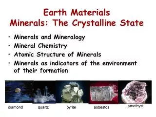
Silicates • The earth’s crustal rocks (clays, soils, and sands) are composed almost entirely (~95%) of silicate minerals and silica (O, Si, and Al). • There exist many structural types with widely varying stoichiometries (replacement of Si by Al is common). Consequences? • Common to all: • SiO4 tetrahedra units • Si is coordinated tetrahedrally to 4 oxygens http://www.soils.wisc.edu/virtual_museum/displays.html http://mineral.galleries.com/minerals/silicate/class.htm
The Tetrahedral SiO4 Unit Cheetham and Day
Structures with the SiO4 Unit • Discrete structural units which commonly contain cations for charge balance. • Corner sharing of O atoms into larger units. • O lattice is usually close-packed (near) • Charge balance is obtained by presence of cations. Individual units, chains, multiple chains (ribbons), rings, sheets and 3-d networks.
Structure Containing Discrete Units • Nesosilicates – no O atoms are shared. • Contain individual SiO44- units. • ZrSiO4 (zircon) – illustrate with softwares • Stoichiometry dictates 8-fold coordination of the cation. • (Mg3 or Fe3)Al2Si3O12 (garnet) – illustrate with softwares • 8-fold coordination for Mg or Fe and 6-fold coordination for the Al.
Structure Containing Discrete Units • The sorosilicates (disilicates) – 1 O atom is shared. • Contain Si2O76- units • Show Epidote (Ca2FeAl2(SiO4)(Si2O7)O(OH)) with softwares. • Epidote contains SiO44- and Si2O76- units • Near linear Si-O-Si bond angle between tetrahedra.
Cyclosilicates (discrete cyclic units) • Each SiO4 units shares two O atoms with neighboring SiO4 tetrahedra. • Formula – SiO32- or [(SiO3)n]2n- (n=3-6 are the most common. • Beryl – six-linked SiO4 tetrahedra (show with softwares). • Be3Al2(SiO3)6 – contains Si6O1812- cyclic units • The impurities produce its colors. • Wadeite – three-linked SiO4 tetrahedra (don’t have an actual picture) • K2ZrSi3O9
Silicates with Chain or Ribbon Structures • Corner sharing of SiO4 tetrahedra (SiO32-) • Very common (usually to build up more complicated silicate structures). • Differing conformations can be adopted by linked tetrahedra. • Changes the repeat distance. • The 2T structure is the most common (long).