Download
1 / 15
150 likes | 284 Views
Unit 9 Multiplexers, Decoders, and Programmable Logic Devices. Ku-Yaw Chang canseco@mail.dyu.edu.tw Assistant Professor, Department of Computer Science and Information Engineering Da-Yeh University. Contents. 9.1 Introduction 9.2 Multiplexers 9.3 Three-State Buffers

E N D
Unit 9Multiplexers, Decoders, and Programmable Logic Devices Ku-Yaw Chang canseco@mail.dyu.edu.tw Assistant Professor, Department of Computer Science and Information Engineering Da-Yeh University
Contents 9.1 Introduction 9.2 Multiplexers 9.3 Three-State Buffers 9.4 Decoders and Encoders 9.5 Read-Only Memories 9.6 Programmable Logic Devices 9.7 Complex Programmable Logic Devices 9.8 Field Programmable Gate Arrays Fundamentals of Logic Design
Introduction • Integrated Circuits (ICs) • SSI : Small-scale integration • MSI : Medium-scale integration • LSI : Large-scale integration • VLSI : Very-large-scale integration Fundamentals of Logic Design
Introduction • SSI • NAND, NOR, AND, OR, inverters, flip-flops • 1 to 4 gates, six inverters, 1 or 2 flip-flops • MSI • adders, multiplexers, decoders, register, counters • 12 to 100 gates • LSI • 100 to a few thousand gates • VLSI : Very-large-scale integration • Several thousand gates or more Fundamentals of Logic Design
IC classification • According to how many transistors were integrated on one single chip: • SSI (Small Scale Integration) : 64 • MSI (Medium Scale Integration): 1,024 • LSI (Large Scale Integration) : 65,000 • VLSI (Very Large Scale Integration) more than 65000 • SVLSI (Super Very Large Scale Integration) : > 500,000 Fundamentals of Logic Design
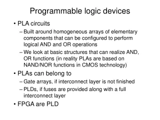
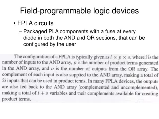
Introduction • Multiplexers • Decoders/Encoders • Three-state buffers • ROMs • PLDs • PLAs • PALs • CPLDs • FPGAs Fundamentals of Logic Design
Contents 9.1 Introduction 9.2 Multiplexers 9.3 Three-State Buffers 9.4 Decoders and Encoders 9.5 Read-Only Memories 9.6 Programmable Logic Devices 9.7 Complex Programmable Logic Devices 9.8 Field Programmable Gate Arrays Fundamentals of Logic Design
Multiplexers • Also called data selector • Abbreviated as MUX • Consist of • A group of data inputs • A group of control inputs • To select one of the data inputs and connect it to the output terminal Fundamentals of Logic Design
2-to-1 Multiplexers • A = 1 • Z = I1 • A = 0 • Z = I0 • Logic equation: Z = A’I0 + AI1 Fundamentals of Logic Design
4-to-1 Multiplexers • Logic equation • Z = A’B’I0 + A’BI1 + AB’I2 + ABI3 Fundamentals of Logic Design
Multiplexers Fundamentals of Logic Design
Multiplexers • A multiplexers with n control inputs • To select any of 2n data inputs • General equation Z = ∑ mk Ik where mk is a minterm of the n control variables and Ik is the corresponding data input 2n-1 k = 0 Fundamentals of Logic Design
Multiplexers • Logic diagram for 8-to-1 MUX Fundamentals of Logic Design
Multiplexers • Frequently used to select the data • To be processed or stored • Quad Multiplexer to select data • A = 0 : x0x1x2x3 • A = 1 : y0y1y2y3 Fundamentals of Logic Design
Bus • A bus • Several logic signals my be grouped together • Represented by a single heavy line. • Number of bits in the bus • A diagonal slash through a bus with a number beside it • A = 0 • X appear on bus Z • A = 1 • Y appear on bus Z Fundamentals of Logic Design