MR – Part IV: Contrast & Sequences
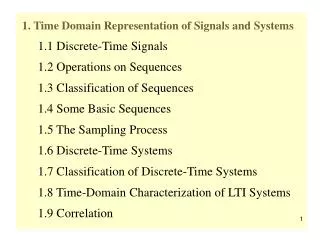
MR – Part IV: Contrast & Sequences. Roland Bammer, Ph.D. Assistant Professor of Radiology (physics course director) 1201 Welch Road, Lucas Center, PS-08 phone: 650-498-4760 e-mail: rbammer@stanford.edu. Gradient Echo Imaging (GRE). TR. no 180° refocusing pulse

MR – Part IV: Contrast & Sequences
E N D
Presentation Transcript
MR – Part IV: Contrast & Sequences Roland Bammer, Ph.D. Assistant Professor of Radiology (physics course director) 1201 Welch Road, Lucas Center, PS-08 phone: 650-498-4760 e-mail: rbammer@stanford.edu
Gradient Echo Imaging (GRE) TR • no 180° refocusing pulse • additional purposeful dephasing of FID by extrinsic field perturbation GRO • unlike SE other field inhomogeneities cannot be undone ! 90° 90° RF Gslice ky GPE GRO ts kx
How to generate a Gradient Echo 90º 90º V t t A2 mT/m A1 Gradient Echo Gradient Echo if A1=A2 ~e-t/T2* mV t TE TR
90º 180º Spin Echo
Spin Echo TE … (Spin) Echo Time (when all spins are in-phase again TR … Repetition Time = time between successive 90-180 … 90-180 RF pulses 180º 90º 90º TE/2 TE/2 V t T2 Spin Echo FID mV t T2* T2* TE TR
Contrast: Summary TE not used T1w PDw T2w TR
Spin Echo vs. Gradient Echo T2wFSE T2*wGRE
Spin Echo vs. Gradient Echo T2w FSE T2*w GRE
Inversion Recovery 180º 180º 180º 90º V t Spin Echo mV t Inversion TimeTI Echo TimeTE Repetition Time TR Improved T1 contrast Keep TE short to avoid mixed contrast
TI 750 TI 550 Mz tissue1 tissue2 t 180° 180° 90° t TI 350 TI 150 TI Inversion Recovery 2D IR, TR = 2500, TE = 14, BW= +16kHz, FOV = 20cm, Thk = 4mm/2, 256x192 , NSA 0.5
Gradient Echo - Echo-planar Imaging (GE-EPI) TR RF Gz Gy Gx Signal
Spin Echo - Echo Planar Imaging (SE-EPI) 180° 90° RF TE/2 TE/2 Gs GPE tacq Prephasor GRO
Fast Spin Echo (FSE)Turbo Spin Echo (TSE) • Acquire Multiple Spin Echoes • Echo Train Length (ETL) or Turbofactor (TF): # Echoes/TR • Each Spin Echo has different phase encoding • Acquire more than one line in k-space • NPE/ETL needed instead of NPE Most Important Sequence
Steady State Free Precession (SSFP) Sequences TR TR << T2 • Transverse magnetization hasn’t disappeared when next RF is played out • Contribution to echo from previous transverse magnetization on top of fresh magnetization • HINT! Read up on stimulated echoes and coherence pathways to understand how SSFP really works! ky ts 2nd Most Important Sequence kx
Gradient Echo Imaging Field Echo (FE) / Gradient Echo (GRE) (T1 > TR >> T2) Fast Field Echo (FFE, GRE)(TR ~ T2 and smaller) Transient Field Echo (TFE) Spoiling net dephasing/TR (q)large net dephasing/TR (q)zero SSFP SPGRT1-FFEFLASH balanced SSFPFIESTA trueFISP balanced FFER-FFE FID:FASTGRASSFISP N-FFE ECHO:CE-FASTSSFPPSIFT2-FFE
Spoiled vs. Unspoiled SSFP Contrast dependence on TR/TE/a 1.5T, FOV=23cm, 256x256, thk=3mm, TR/TE=15/5.2ms, NEX=4 spoiling no spoiling spoiling no spoiling a=40 a=4 a=4 a=40 a=90 a=90 a=20 a=20 (RF or Gradient) spoiling = crushing Mxy after echo formation
flow static spins saturated by repeated excitation inflow of magnetized spins flow TOF - Flow Related Enhancement Mz t
2D-TOF - Spatial Presaturation arterial venous
Phase Contrast MRA • exploits flow/motion induced phase shifts • need reference image for velocity in 1 direction difference in 2 measurements for all 3 velocity components 4 measurements with flow probing gradients amplitude of flow probing gradients determine venc lots of data (vx, vy, vz), “speed”, anatomy • longer scan times • can be quantitative
Basic Principle of PC MRI Echo 1 Echo 2 Echo 3 Echo 4 Gx Gy Gz RF Sign. vx-flow Echo 2 - Echo 1 vy-flow Echo 3 - Echo 2 vz-flow Echo 4 - Echo 3