Download
1 / 1
40 likes | 295 Views
Mass. driving fingers. driving fingers. silicon bonding frame. driving beams. sensing mass. sensing beams. Silicon (fixed). Silicon (floating). MEMS Gyroscope with Electrostatic Comb Actuation and Differential Capacitance Sensing Haifeng Dong, Zheng Yao, Advisor: Xingguo Xiong

E N D
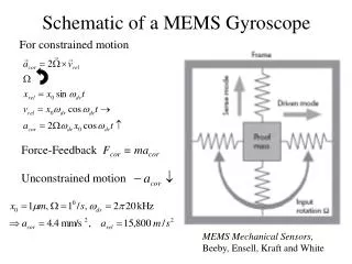
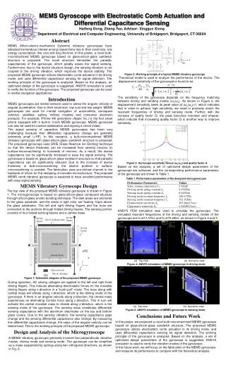
Mass driving fingers driving fingers silicon bonding frame driving beams sensing mass sensing beams Silicon (fixed) Silicon (floating) MEMS Gyroscope with Electrostatic Comb Actuation and Differential Capacitance Sensing Haifeng Dong, Zheng Yao, Advisor: Xingguo Xiong Department of Electrical and Computer Engineering, University of Bridgeport, Bridgeport, CT 06604 Abstract MEMS (Micro-electro-mechanical Systems) vibratory gyroscopes have attracted tremendous interest among researchers due to their small size, low energy consumption, low cost and long life-time. In this poster, a novel bulk-micromachined MEMS gyroscope based on glass-silicon-glass sandwich structure is proposed. The novel structure eliminates the parasitic capacitances of the gyroscope, which greatly eases the signal sensing. Furthermore, due to the device structure design, the sensing vibration is not coupled to the driving vibration, which improves the device stability. The proposed MEMS gyroscope utilizes electrostatic comb actuation in its driving mode, and uses differential capacitance sensing for signal detection. The working principle of the gyroscope is analyzed. Based on the analysis, an optimized design of the gyroscope is suggested. ANSYS simulation is used to verify the function of the gyroscope. The proposed gyroscope can be used in inertial navigation applications. Figure 2: Working principle of a typical MEMS vibratory gyroscope Theoretical model is used to analyze the performance of the device. The displacement sensitivity of the gyroscope is found to be The sensitivity of the gyroscope depends on the frequency matching between driving and sending modes (ωx/ωy). As shown in Figure 3, the displacement sensitivity takes its peak value at (ωx/ωy)=1, which indicates that in order to achieve high sensitivity, we need to precisely match the resonant frequencies of driving and sensing mode. Further, with the increase of quality factor Q, the peak becomes narrower and sharper, which indicate that increasing quality factor Q is another way to improve sensitivity. Introduction MEMS gyroscopes are inertial sensors used to sense the angular velocity or angular acceleration. Due to their small size, low cost and low weight, MEMS gyroscopes are used for inertial navigation of automobiles, aerospace vehicles, satellites, sailing, military missiles and consumer electronic products. For example, iPhone 4th generation (Apple Inc.) is the first smart phone equipped with a built-in 3-axis MEMS gyroscope. MEMS gyroscope can also be used for camera stabilization and signing a check midair. The signal sensing of capacitive MEMS gyroscopes has been very challenging because their differential capacitance change are generally extremely small (<1fF). In this research, a bulk-micromachined MEMS vibratory gyroscope with glass-silicon-glass sandwich structure is proposed. The proposed gyroscope uses DRIE (Deep Reactive Ion Etching) technique so that the device thickness can be increased from several microns (in surface-micromachining) to hundreds of microns. As a result, the device capacitance can be significantly increased to ease the signal sensing. The gyroscope is based on glass-silicon-glass sandwich structure so that parasitic capacitance can be significantly reduced. Due to the increase of device thickness in bulk-micromachining, the stiction problem in surface-micromachining is avoided. The fabrication uses pre-etched channel in the backside of silicon for the releasing of movable microstructure. The proposed MEMS comb vibratory gyroscope is expected to have excellent performance with easy signal sensing. z Figure 3: Gyroscope sensitivity versus(ωx/ωy) and quality factor Q Based on the analysis, a set of optimized design parameters of the gyroscope are achieved, and the corresponding performance parameters of the gyroscope are shown in Table 1. Table 1. Performance parameters of the designed microgyroscope MEMS Vibratory Gyroscope Design The top view of the proposed MEMS vibratory gyroscope is shown in Figure 1. The microgyroscope is based on glass-silicon-glass compound structure through silicon-glass anodic bonding technique. The dark areas are anchored to the glass substrate, and the areas in light color are floating 10μm above the glass substrates. The left and right driving fingers and the truss are connected to the anchors through folded driving beams. The sensing portion consists of four folded sensing beams and a central mass. ANSYS FEM simulation was used to simulate the gyroscope. The simulated resonant frequencies of the driving and sensing modes of the gyroscope are fx=617.37Hz and fz=675.46Hz, as shown in Figure 4 and 5. y(Ω) x (a). Top view (b). Isometric view Figure 4: ANSYS simulation of MEMS gyroscope in driving mode z Figure 1: Schematic diagram of the proposed MEMS gyroscope During operation, AC driving voltages are applied to the left and right fixed driving fingers. This induces alternating electrostatic forces on the movable driving fingers along x-direction in a "push-pull" mode. The truss along with central mass will vibrate along x-direction, which is the driving mode of the gyroscope. If there is an angular velocity along y-direction, the central mass experiences an alternating Coriolis force along z-direction. This in turn will activate the central movable mass to vibrate along z-direction, which is the sensing mode of the gyroscope. The sensing mass constitutes differential sensing capacitance with the aluminum electrodes on the top and bottom glass covers. Due to the sensing vibration, the sensing capacitance gaps change and the sensing differential capacitance also change. By measuring this differential capacitance change, the value of the angular velocity can be determined. This is the working principle of the proposed MEMS gyroscope. (a). Top view (b). Isometric view Figure 5: ANSYS simulation of MEMS gyroscope in sensing mode Conclusions and Future Work In this poster, we proposed a novel bulk-micromachined MEMS gyroscope based on glass-silicon-glass sandwich structure. The proposed MEMS gyroscope utilizes electrostatic comb actuation in its driving mode, and uses differential capacitance sensing for signal detection. The working principle of the gyroscope is analyzed. Based on the analysis, a set of optimized design parameters of the gyroscope is suggested. ANSYS simulation is used to verify the vibration modes of the gyroscope. In the future work, we will focus on the fabrication of the MEMS gyroscope, and measure its performance to compare with the theoretical analysis. Design and Analysis of the Microgyroscope A MEMS vibratory gyroscope generally involves two perpendicular vibration modes: driving mode and sensing mode. The gyroscope can be simplified as a mass suspended by springs along two orthogonal directions, as shown in Fig. 2.