Download
1 / 32
320 likes | 532 Views
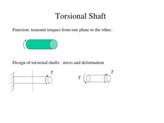
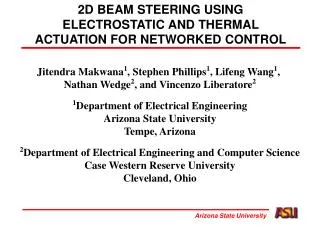
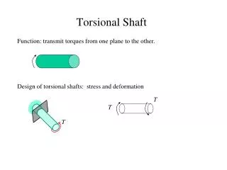
Vertical electrostatic actuation of torsional mirrors. A typical 1 axis torsional mirror. Flat, reflective mirror. Torsional spring. Electrostatic actuators. Vertical electrostatic actuation: problems. Large angle + stability large gaps Large gaps small forces small torque

E N D
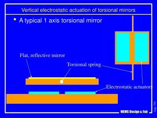
Vertical electrostatic actuation of torsional mirrors • A typical 1 axis torsional mirror Flat, reflective mirror Torsional spring Electrostatic actuators
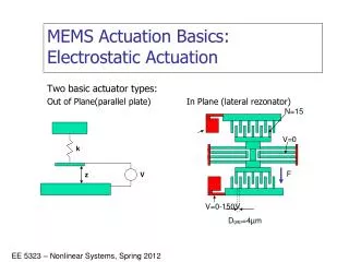
Vertical electrostatic actuation: problems • Large angle + stability large gaps • Large gaps small forces small torque • Small torque flimsy springs • Flimsy springs low resonant frequency!
Mirror design • Reflective mirror metallic coating • Metallic coating thermal bimorph • Curvature requirement thick silicon • Thick silicon higher mass slow mirror
2DoF Micromirror anchor Back-side etched cavity anchor
Challenges with this methodology z Lateral pull y x Low SCS beam/structure must be compliant in zand stiff in x, y Performance is aspect-ratio limited => highSCS beam is too stiff Lateral actuation displaces the mirror laterally
Challenges – Lateral displacement Very little rotation due to vertical stiffness of low SCS yank leg Lateral pull dominates actuation
Bond/transfer results Long HF Release of TopSCS handle wafer Target wafer is a regular Si wafer
Optical Comm Proof of Concept Receiver • 1” lens, std. video CCD • PCMCIA Frame grabber • Software decoding Laser transmitter • 4bps OOK • Laser pointer (Radio Shack)
Laser Comm at 5.2 km Received by a CCD video camera with 3” aperture. During daylight, through light rain. • 14 microW, ~1mrad • 8 mW, ~1mrad • 3 mW, ~100mrad
Simulation of CCR reflection Goal: predict impact of diffraction and non-flat, non-perpendicular mirrors Methodology: Divide faces into discrete rectangular elements Perform ray-tracing to determine direction and phase of each ray Sum Fraunhofer diffraction integrals from discrete elements. Author: Victor Hsu (with Joe Kahn, K. Pister, UCB; contact jmk@eecs.berkeley.edu)
1m rad 8m rad CCR Differential Scattering Cross-section Angle error, 1 side (Courtesy: Lixia Zhou, UCB lzhou@eecs.berkeley.edu) 0.5m rad
AR coated dome lens Steering Mirror laser CMOS ASIC 2D beam scanning
6-bit DAC Driving Scanning Mirror • Open loop control • Insensitive to disturbance • Potentially low power
~8mm3 laser scanner Two 4-bit mechanical DACs control mirror scan angles. ~6 degrees azimuth, 3 elevation
Optical Communication Path loss 0-25% 25% Loss = Areceiver / (4p d2) / Gant Antenna Gain = 4p / q½2
Theoretical Performance 5m Ptotal = 100uW Pt = 10uW q½ = 1mrad BR = 5 Mbps Areceiver = 0.1mm2 Pr = 10nW (-50dBm) Ptotal = 50uW SNR = 15 dB 20pJ/bit!
Theoretical Performance 500km Ptotal = 50mW Pt = 5mW q½ = 1mrad BR = 2 Mbps Areceiver = 1m2 Pr = 10nW (-50dBm) Ptotal = 50uW /pixel SNR = 17 dB 25nJ/bit!
Augmented Reality Lau, Muller, Solgaard and students
G R B Laser pointer projector 2D RGB projector • Stabilized laser pointer • Hand-held projector • Virtual whiteboard • Track user motions while drawing • Refresh at 30 Hz Erase Clear 3axis gyro
RGB(x,y) RGB(x,y,a,b) Displays and screen doors Array of pixels Screen door Display
Virtual window Pixel array Each pixel like a pinhole camera Max pixel power: 5mW out, 5mm^2 Array power (out): 1kW/m^2 Power in: 50mW/pixel Power in: 10kW/m^2 !
HDTV window Pixel array • 2000x1000 array • 1mm^2, 1mW out pixels • Full video on each pixel • Optical power out: 2kW • Shadows • Heat! (w/o sunburn) • Home defense • Uncompressed data rate: ~20 Tbps
HDTV window – more realistic Pixel array • Eye tracking (multi-user) ~25/cones/pixel/face Data rates ~few video streams • 10W/m^2 (bright indoor) 10uW/pixel average Array power << kW For each pixel For each face draw 5x5 grid ;