Download
1 / 21
210 likes | 339 Views
LHCI – Injector Accelerator for the LHC Motivation. Inject 1.5 TeV proton beams to LHC instead of the current 0.45 TeV beams from the SPS At this new energy the field harmonics [1] of the LHC magnets are satisfactory enough to prevent luminosity losses expected with the

E N D
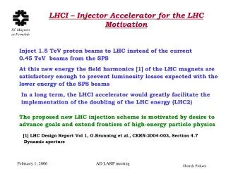
LHCI – Injector Accelerator for the LHC Motivation • Inject 1.5 TeV proton beams to LHC instead of the current • 0.45 TeV beams from the SPS • At this new energy the field harmonics [1] of the LHC magnets are • satisfactory enough to prevent luminosity losses expected with the • lower energy of the SPS beams • In a long term, the LHCI accelerator would greatly facilitate the • implementation of the doubling of the LHC energy (LHC2) • The proposed new LHC injection scheme is motivated by desire to • advance goals and extend frontiers of high-energy particle physics • [1] LHC Design Report Vol 1, O.Brunning et al., CERN-2004-003, Section 4.7 Dynamic aperture AD LARP meeting
LHCI Proposal – Brief History Lucio Rossi of CERN proposed (9/05) to consider an Injector Accelerator (LHCI) based on the VLHC low field magnets to boost the initial energy of the proton beam in LHC HP with help from Gijs de Rijk (CERN) investigated feasibility of the LHCI ring in the LHC tunnel during 3 weeks stay at CERN in 10/05, and produced a report indicating that the LHCI magnet ring can be installed in the LHC tunnel but the beam injection from the LHCI to LHC is a very difficult problem John Johnstone and Tanaji Sen (11/05) begun investigating the LHCI lattice and the design of the transfer lines From 11/05 HP is discussing with Vl. Kashikhin options for fast kicker magnets, and with Steve Hays matching power supplies AD LARP meeting
Elected Boundaries for LHCI Injector Accelerator Design • - LHCI will fit inside the LHC tunnel without major modifications • - LHCI magnet ring will be installed using regular LHC shutdowns • - The current SPS-LHC injection scheme will remain intact, and • it will be used to inject beams to the LHCI • - A reversal to the standard SPS-LHC injection scheme will be possible at any time after implementation of the LHCI • - The LHCI accelerator components will be designed using • primarily known technologies, so only the prototyping will • be necessary thus allowing to proceed with LHCI design now AD LARP meeting
Proposed LHCI – LHC Injection Scheme The new injection scheme shows only the path from SPS to LHCI to LHC AD LARP meeting
VLHC Low Field Magnet for the LHCI VLHC: - 233 km accelerator ring - ~ 3200 main arc dipoles - ~ 466 km continued length of transmission line superconductor LHCI: - ~27 km accelerator ring - 1232 main arc dipoles - ~ 54 km continued length of transmission line superconductor AD LARP meeting
Base Magnet of the LHCI Accelerator • Magnet cross-section area: 26 cm (height) x 24 cm (width) • 1.8 Tesla field (nominal operation) • 0.6 Tesla (beam injection) • 20 mm magnet pole gap • Energized by 100 kA, single turn transmission line superconductor • Coolant – supercritical helium (4.2 K, 4 bar, 60 g/s) • Warm beam pipe vacuum system (ante-chambers required) • Alternating gradient 16 m We propose that LHCI is based on the VLHC Low Field magnet AD LARP meeting
LHCI Magnet Location in the LHC Tunnel • It fits easily in the space above the • LHC magnet • Minimum vertical distance between • LHC and LHCI beams: 1100 mm • The holding brackets and the magnets • can be installed without disturbing the • LHC operations • The LHe can be tapped at convenient • locations from the QRL line (1600 g/s) AD LARP meeting
LHCI Arc Dipole Magnet in LHC Tunnel Normal tunnel area Area with cryogenic feed tower AD LARP meeting
VLHC Low Field Magnet Tests • Test gradient dipole magnet - 1.5 m long • Transmission line superconductor – 16 m long • Current leads: 100 kA (RT->LHe) • Power supply: 100 kA dc • Quench detection & protection system: standard • Magnetic measurements: - Tangential coil: 0.7 m long, 15 mm diameter - 102 element Hall Array • Supporting cryogenics - Two – phase LHe at ~ 5 K - Three independent flows of 6 g/s each AD LARP meeting
100 kA dc Power Supply • Steven Hays: MOA04P001 • 1.5 V @ 100 kA Switcher Power • Supply was used as both: • - Ramping supply, and • - Holding supply • It consists of: - Bulk 400 V, 240 kW filtered and regulated supply - 10 switcher cells connected in parallel at the input to the magnet current leads Operated as constant power device: No regulation was available for using the load current, or magnetic field AD LARP meeting
100 kA dc Current Leads • Yuenian Huang: WEA03PO04 • Lead: 202 Cu rods, 1650 mm long, • 6.35 mm dia. • Est. heat transfer: 200 W/m2_K • Temperature profiles: • Blue dots – no current • Purple square: 90 kA, stable • Red triangles: 100 kA, 5.6 g/s, • stable for 15’ AD LARP meeting
Magnet and B-field Measuring Instrumentation • Magnet view (tangential coil side) Magnet view (Hall station side) AD LARP meeting
Magnetic Measurements Gueorgui Velev, TUA07PO02 Probe: 15.2 mm dia. x 754.1 mm long Vespel (polyimide) used to form the probe (winding support) and bearings. Field Harmonics measured to: order 10 at 1.966 Tesla (collisions), and order 6 at 0.1 Tesla (injection) AD LARP meeting
Magnetic Measurements • Quadrupole component is as designed; ~ -415 units, both at • injection and full field 1.966 T. • 102 element Hall Probe confirms • the +/- 4% gradient. • Sextupole component very small; • ~ few units, and no change from • injection to the full field 1.966 T. • The b4 – b10, and the a4 – a10 • also << 4 units, or << 0.04%. AD LARP meeting
VLHC Low Field Magnet Team Members of the VLHC Low Field Magnet Group: Ruben Carcagno, Brad Claypool, George W. Foster, Steven Hays, Yuenian Huang, Vladimir Kashikhin, Ernest Malamud, Peter Mazur, Roger Nehring, Andrew Oleck, Henryk Piekarz, Roger Rabehl, Phil Schlabach, Cosmore Sylvester, George Velev, James Volk (FNAL) and Masayoshi Wake (KEK) Five papers published at MT-19, Genoa, Italy, 2005 AD LARP meeting
Principle of the LHCI-LHC Beam Transfer • After the LHCI ring filling is complete, the kicker magnets are turned • off as soon as the last proton bunch passed through them. AD LARP meeting
LHCI-LHC Transfer Line Boundaries • LHC-LHCI vertical separation: 1100 mm • LHC beams separation: 194 mm ( LHCI: 150 mm) • Total length of ½ of straight section: 260 m • Total available free space between D1 and Q7: 176.5 m AD LARP meeting
LHCI Beam Pipe Inside the LHC Magnets • LHCI beam pipes can be inside • the LHC magnet cryostat. This • allows to minimize to 170 mm • the required LHCI beam • deflection in the Kickers • The fringe B-field outside the • yoke is very small , and so is • the heat load of the LHCI pipe • Modification of LHC magnets • can be done using the spares, • and then swapping them with • those in the tunnel AD LARP meeting
Fast Kicker Magnets A B • A conceptual view of the fast kicker magnet arrangements: • - LHCI and LHC beam share the beam pipe • - LHCI and LHC beams are separated AD LARP meeting
Fast Kicker Magnet Power Supply • Magnet gap: 6 cm => 4 T, 90 kA, 30 KV @ 3 usec & 1 uHenry AD LARP meeting
Schedule & Cost • Construction 5 – 6 years, and $150 M of total cost AD LARP meeting