Experience with Parallel Optical Link for the CDF Silicon Detector
250 likes | 393 Views
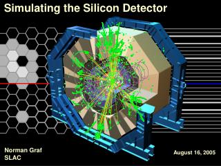
Experience with Parallel Optical Link for the CDF Silicon Detector. S. Hou for the DOIM group Academia Sinica, Taiwan. Introduction. DOIM: D ense Optical Interface Module Byte-wide parallel optical link 8-bits + clock 53 Mbyte/sec, BER 10 -12 Transmitter : Laser-diode array

Experience with Parallel Optical Link for the CDF Silicon Detector
E N D
Presentation Transcript
Experience with Parallel Optical Link for the CDF Silicon Detector S. Hou for the DOIM group Academia Sinica, Taiwan VERTEX 2002
Introduction • DOIM: Dense Optical Interface Module • Byte-wide parallel optical link • 8-bits + clock • 53 Mbyte/sec, BER10-12 • Transmitter : • Laser-diode array • ASIC driver chip • Receiver : • PIN-diode array • ASIC receiver chip • Multi-mode fiber ribbon • Laser, Electrical characteristics • Bit-error rate test • Aging test • Radiation Hardness • Implementation in CDF VERTEX 2002
Transmitter: Laser diode • InGaAs/InP Edge-emitting laser diode : • 1550 nm wavelength • 12-ch diode array (9 used) • 250 m pitch • 20 mA/channel • Cleaved mirrors • Facet coating • Bare laser power: • 1 mW/ch @20mA • Insertion to fiber: • 200 ~ 800 W/ch • Fabrication by • Chunghwa Telecom • Telecommunication Laboratories VERTEX 2002
Transmitter: driver ASIC • Custom design, biCMOS 0.8 m,AMS • bipolar transistors only • Inputs : • Diff. ECL or LVDS signals compatible • differential 100 mV • Enable by TTL low • Nine channels : • Vcc-VLD across • output transistor, 50 , laser • control current consumption • At 3V, 20mA/ch nominal • ~2mA/0.1V adjustable slope VERTEX 2002
Transmitter assembly • Die-bond / Wire bond • laser-diode array on BeO submount • driver chip on substrate • fibers on V-groove • Alignment • fibers to laser emitting facets VERTEX 2002
Receiver : PIN & ASIC • InGaAs/InP PIN diode : • 12-ch array, matching laser diode wavelength • by TL, Chunghwa Telecom. • Operation condition : • 50 ~ 800 W on, 10 W off • 1.1 W/module • Outputs : • differential ECL,nine independent channels VERTEX 2002
Receiver assembly • Die-bond / Wire bond • PIN-diode array on Al2O3 submount • driver chip on substrate • fibers on V-groove • Alignment, fibers to PIN-diodes VERTEX 2002
Assembly procedure VERTEX 2002
Transmitter characteristics • Transmitter tests : • L-I-V and temperature • 50 MHz diff. Inputs, 2.5V common mode 100 mV, 50% +Dcyc • Laser light MT-12ST fanout & Tek O/E probe VERTEX 2002
Laser diode: L-I-V • Laser light at 20, 30, 40oC • water-bath chiller precision ~0.1oC • measured at substrate • I-V • little temperature dependence • approximately linear • L-V • Drop with temperature • Duty cycle • diff. Input 50% • stable, little offset to 50% VERTEX 2002
Laser diode: temperature • Light power vs. Temperature • Measured in stable • cooling/heating process • Temperature at substrate • precision ~0.1oC • Approximately linear drop • to temperature VERTEX 2002
Receiver response • Receiver connected to a Transmitter • Light power chosen for • wide distribution • Light pulse width are consistent • Receiver ECL outputs • by a Tektronix diff. probe • Consistent duty cycles in favored operation range (2.8~3.2V) • Saturates for high light level VERTEX 2002
Transmitter uniformity : light outputs • Production transmitters • light from pigtail at 30oC • wide deviation channel-by-channel • mainly due to insertion efficiency • Span within ~400 W • ~72 W to the mean/module • Effect operation dynamic range in • threshold, saturation limit VERTEX 2002
Transmitter uniformity : light pulse widths • Ch-Ch Light power deviation • Is approximately a const. scaling factor • L-V linear fit, normalized slope to L(3V) indep. of light power • Light pulse width is uniform, ~1%, indep. of light power VERTEX 2002
Receiver uniformity : ECL duty cycles • Two production batches • monitored at 550 W & 970 W • light pulse width 45% • ECL duty cycle is uniform • 48.1% at 550 W, (2nd batch) • =0.7% • 4% wider in 1st batch • due to chip tuning • Wide light input range • Saturation monitored at 970 W VERTEX 2002
Receiver uniformity : duty cycle deviation • Input lights • ~950 W, width 45% • for all channels • ECL outputs of a module • deviation to the mean • ~1.5% • for both batches VERTEX 2002
Bit-Error Rate test • BERT by Fermilab • PC ISA boards TTL to • Tbert, Rbert boards • At 63 MHz, • minimum BER 10 –12 • Burn-in • 3-days on ASICs, diodes • 1-day BERT • reject devices infant mortality • bad components fail quickly VERTEX 2002
Accelerated Aging test • 4 transmitters at 60oC, 330 days • Wear-out degradation • 0.15 0.08 W/day at 60oC • no failure • Accelerating factor • F=exp(Ea/kb) (1/T1 –1/T2) • F=29 for T= – 5oC • Failure due to light degradation • Min transmitter spec 200 W • down below receiver threshold 50 W • ~100 days at 60oC, or 8 years at – 5oC • 90% C.L. for 0 failure, P=0.064 • upper limit = 40 ch. In 3 years VERTEX 2002
INER 30 MeV proton Irradiation • CDF requirement : 200 kRad tolerance • INER test beam : transmitter in DC mode. • fiber connection out of beam area, measuring L, T versus dose. VERTEX 2002
Bulk damage, annealing • Bulk damage dominant, linear dep. to dose • Ratio of light drop is consistent for a module, indep. of light power • Degradation10% for 200 kRad VERTEX 2002
UC Davis 63.3 MeV proton • UC Davis test beam : 10 transmitters on two Port Cards • Examined after 200, 400 kRad, for L I, V measurements • Light degradation ~10% for 200 kRad • Similar I-V, L-V characteristics after irradiation, • slope for L vs. V degrades similarly. VERTEX 2002
DOIM implementation : transmitters • Transmitters on Port Cards • Total 570 transmitters • 128 Port Cards, • 5 transmitter each board VERTEX 2002
DOIM implementation : receivers • Receivers on FTM • 10 receivers on each board, reading 2 Port Cards VERTEX 2002
Status • 570 pairs implemented • ~10 % bit-error flagged • excess light at -5oC • optical reflection, contact • electrical pin contact • 2% has fatal damage • is improving VERTEX 2002
Summary • DOIM, a byte-wide optical link is implemented in CDF • Edge-emitting laser light linear to I-V and T • Laser-diode array coupling to pigtail fibers • large deviation a major disadvantage • Radiation tolerance is high • bulk-damage dominant linear degradation to dose VERTEX 2002