Download

1 / 8
80 likes | 200 Views
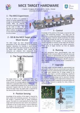
Mice Target Stator Field Mapping G Barber, E Longhi, C MacWaters, P Smith, J Tarrant & Many others. Mice Target Stator Field Mapping. Contents:- Design of the Rig Services Mapping Procedure Future Work. Design of the Rig.

E N D
Mice Target Stator Field Mapping G Barber, E Longhi, C MacWaters, P Smith, J Tarrant & Many others
Mice Target Stator Field Mapping • Contents:- • Design of the Rig • Services • Mapping Procedure • Future Work
Design of the Rig The Rig we are using is in R79 and belongs to the Diamond Insertion Devices Group. It consists of a large 3 axis stage (the largest is ~5M a little excessive), a 3 axis Hall probe and readout system. The 3D model shows a layout of the system
Design of the Rig (cont) The Plan is to bolt a frame onto a granite support block at the end of the existing test rig. This we hope will cause the minimum inconvenience to our hosts. The 3D model and photos show the stator support frame with kinematic mount.
Services • The setup requires the following services :- • Power Supply • Water Chiller • Electronic Controller
Mapping Procedure The mapping procedure will be carried out by Emily Longhi who will determine the method and techniques required. Because of the non symmetry of the hall probe ‘wand’, see below, it may be necessary to rotate the stator, rotate the wand or a combination of both. If it is necessary to rotate the stator the original 4 mounting holes enable measurements to be taken every 90° we have added a second set of mounting holes to the rig which allows measurements every 45°
Services • The setup requires the following services :- • Power Supply • Water Chiller • Electronic Controller
Future Work Any Future work will largely depend on what we find from the initial tests and how we can make the apparatus more user friendly. As we aare relying on the good will of another group it would be preferable to make the procedure as smooth and quick as possible. I can for example envisage a rotary stage to quickly change the angle of the stator. A second line of work will be to devise a method of mapping the individual coils before they are fitted so it is possible to assemble along a common magnetic axis