Download

1 / 18
180 likes | 294 Views
This paper reviews the performance evaluation and failure analysis of bearing mechanisms used in the MICE (Muon Ionization Cooling Experiment) facility at the University of Sheffield, presented by Paul Smith and based on Chris Booth's earlier talk. It details two types of bearings (DLC on DLC and Vespel on DLC), their installation, actuation counts, and failure characteristics. Key findings include stable operation up to 2.15 million pulses, with minimal dust production and insights on target performance diagnostics over time. The analysis highlights potential improvements in design for future applications.

E N D
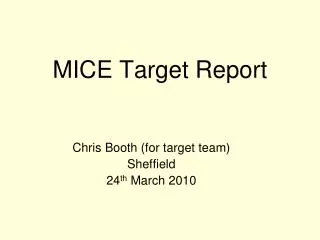
MICE Target Mechanism Paul Smith University of Sheffield 8th June 2010 (Based upon talk given by Chris Booth at CM26)
History & Overview • T1 – DLC bearings – running in ISIS (Installed Aug 2009) • > 215k + 50 k actuations - DLC on DLC • T2 – nominally identical to T1 • Bearing failed rapidly - DLC on DLC • T2.2 – like T1, improved QA • Failed after ~80k actuations - DLC on DLC • T2.3 – same stator & shaft as T2.2 • New Vespel (polyimide) bearings – Vespel on DLC • Tested for >2.1M pulses in R78 Jan/Feb 2010 Results of T1 running, T2.3 tests, and plans P J Smith - University of Sheffield
Actuation Strike Beam Centre Distance (BCD) P J Smith - University of Sheffield
BCD (beam centre distance) DAQ Analysis(analysis by Paul Hodgson) T1 • T2 distribution 3-4 times as broad • Can be interpreted as a result of the target “sticking” due to adhesive pick-upof particulate DLC - wear. Confirmed when taking target apart– Mice note 269 • MICE use the BCD histograms as a diagnostic to spot changes in target performance T2 4 P J Smith - University of Sheffield
Overlay of T1 Calibration Plots Represents 71K to 142K Actuations P J Smith - University of Sheffield
Summary for Target 1 • Target continues to perform reliably (> 215k + 50 k actuations) • No sign of significant change in BCD distributions • No sign of dust production on view port – Latest photo 07/06/2010 – No Dust • Target keeps running! P J Smith - University of Sheffield
Status of Target 2.3 • T2 Vespel installed in R78 Jan 25th 2010 • DLC coated shaft (from T2.2) – Vespel bearings • Same stator body as previous T2 • Pulsed target continuously for 2.15×10⁶ pulses • Approx. one month of operation at ~1 Hz • Two short interruptions, chiller failed 1/2/2010, UPS failed 8/2/2010(!) • Neither problem associated with target mechanical performance • Target was deliberately stopped for inspection • Very little dust on view-port (~ daily photos) P J Smith - University of Sheffield
T2 BCD over month Early Mid Late 1×10⁶ pulses Change over ~1 day Start up period DAQ gain changes 720k s 1680k s P J Smith - University of Sheffield
T2 Acceleration over month Chiller failure UPS failure Test power off P J Smith - University of Sheffield
T2 Acceleration regions Late Mid Early Steady decline 848 to 838 ms-2 Increased variability Stable operation (838 ± 5) ms-2 720k s 1680k s P J Smith - University of Sheffield
Questions and Comments • How would the target have performed if we had carried on pulsing ? • Remember we arbitrarily stopped at 2.15 × 10⁶ pulses. • Does the early period correspond to the target “bedding in” ? • The mid period lasted approx. 1 million pulses where the target showed stable operation. • There was a reasonably rapid (1 day) change in performance after which the target parameters were (slightly) more variable. • None of the variation seen above would compromise the normal target operation. • The typical beam centre varies more than the target BCD. 11 P J Smith - University of Sheffield
Disassembly & Inspection of Target 2(Jason Tarrant) • Target stopped after 2.16M actuations • Optics block removed & upper bearing exposed • Bellows removed & lower bearing exposed • Significant amounts of Vespel dust, adhered to surfaces P J Smith - University of Sheffield
Disassembly – View of upper Bearing First look Little dust (polished flat) Most dust (rough flat) Dust On shaft, On bearing, On lock ring Rough flat Survey point Polished flat Amalgamated dust balls P J Smith - University of Sheffield
Disassembly – View of lower Bearing External face Dust around bearing, lock ring removed Internal face P J Smith - University of Sheffield
Observation – Dust • Amount • Most at upper bearing – esp. anti-rotate rough flat side • (Only one flat on shaft polished) • Amalgamated at bearings – scraped off • Location • Coated internal components, has escaped externally • How does it move / defy gravity? • Thrown off? • Electrostatic attraction? • Vibration movement? • When let up to air? • Attachment • Fixed – by what? P J Smith - University of Sheffield
Stator QA • Is stator 2 different from stator 1? • Stator field mapped with assistance of group at Diamond • Indication of ~300um offset in magnetic axis. Note: This value is to be re-checked! • Stator willbe run in R78 with bearings aligned with the offset. Will this improve wear rate? An FE model of the stator has been built, the predicted forces match the observed forces very well. The model predicts strong lateral forces if shaft is not aligned with magnetic axis (for 500m offset max lateral force = 10% thrust Force) The modelling and field measurements suggest that we need to improve the coil design/manufacture to ensure magnetic axis aligns with the geometric axis. P J Smith - University of Sheffield
Next Steps • Reduce wear & dust production - Polished flats, burnished bearing faces - Continue using Vespel (but there are additional plastics that can be tried) - Align bearings with known magnetic offset • Trap dust in catcher • Further tests to start in June P J Smith - University of Sheffield
Summary • Target 1 installed and operating well in ISIS • Target 2 with plastic bearings performed reliably for >2M actuations • Stopped for inspection, not due to failure • Test & measurement programme for reducing and trapping dust • Stators have been magnetically mapped to improve QA – indication that there is a magnetic offset with stator 2. P J Smith - University of Sheffield