Download
1 / 34
340 likes | 532 Views
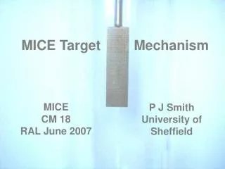
MICE TARGET STATUS. 23 rd February 2007 CM17 - CERN Paul J Smith University of Sheffield. Talk is in 2 parts:. MICE target tests 1-2 nd November & Analysis of results Further Progress in Target Development since Target Tests. Part 1. Target tests 1 st – 2 nd Nov 2006.

E N D
MICE TARGET STATUS 23rd February 2007 CM17 - CERN Paul J Smith University of Sheffield
Talk is in 2 parts: MICE target tests 1-2nd November & Analysis of results Further Progress in Target Development since Target Tests.
Installation - October • MICE beam pipe installed in ISIS, pumped down • Target drive on support frame connected above gate valve • Cables & optical fibres laid between MICE hall & ISIS vault • Control electronics & Lasers installed in MICE hall • Power electronics installed in ISIS vault • Scintillators installed by wall of ISIS vault • 10 m from target, at correct production angle
Target drive in place Photos courtesy of Chris Nelson & Paul Drumm!
Instrumentation • ISIS signals: • Machine Start (MS) synchronisation signals • Beam loss monitors - Section 7 Beam loss - Total Beam loss from all sections • Two RAL scintillators, in shielded box • Two small Glasgow scintillators • Target position readout All digitised on scopes and read out by PC. • Temperature monitoring of the target mechanism
Problems • Two mono-mode fibres damaged during installation beyond use • No exact replacements in Europe and not enough time to have them made in USA! • Specialist company located in the lake district to splice pigtails onto new fibres! • 4 -channel semiconductor laser stopped working • Revived several days later! • (but another laser later stopped working for several hours) • Suspect noisy mains as UPS prevented the problem recurring • No motor drive for jacking mechanism • Required accesses to operate by hand, at start & end of shifts • Problem with limit switches prevented gate-valve operation • Was fixed when we were allowed access
Test Information • Target drive electronics only 10 A max. • Only capable of modest accelerations – cycle time of ~65ms • ISIS running at 50 Hz 64 • Pulse every 1.28 s • Survey run on night of Wed 1st Nov. • No signals into DAQ (The connector ‘Pixies’ had been!!). (Phone calls to control room!) • Full run on night of Thu 2nd Nov. • Two target modes: • Held static at various depths (to find beam size at injection) • Maximum amplitude pulses (~50mm), initially late then the timing was advanced to meet beam
December Tests • We had planned to go back into ISIS and do some further tests the week before Christmas using the upgraded power electronics from Daresbury. (with 40A of current available.) • The power electronics unit failed a couple of days before we were due to go to RAL! • We still went ahead and installed our electronics as Glasgow/RAL wished to collect more data at the lower target insertion current (10A). • BUT…One of the previously repaired fibres had been damaged and prevented us from running.
Analysis • Analysis of scintillator data continuing in Glasgow & RAL • Beam loss studies in Sheffield • “On-line” conclusions: • Beam is much smaller at injection than expected! (Does not “nearly fill the pipe”) • It has a hard edge • Present state of analysis – from beam loss (see plots) • Acceleration of target was only just adequate to sample beam at extraction • Beam (halo) reaches maximum size ~2 ms after injection • With optimum timing, target just scraped the shrinking beam through the ISIS cycle • Beam shrinkage is ~16 mm • This analysis along with a fuller explanation of the plots and graphs will shortly be made available as a mice note.
Beam loss versus position Injection Extraction
Beam loss versus position Losses after ~2 ms Losses at extraction
Beam Loss Profile at ISIS Beam Edge as a Function of Time Built up by Measurements over Slightly Different Trajectories Edge of pipe extraction injection
Profile of the Beam Edge (Time Slices) Examples of 4 of the time slices out of the 100 or so produced! X-axis: Distance from the beam Centre Y-axis: Relative Beamloss
Plot courtesy of Lara! Examples of typical target trajectories during November tests Sample slice (As previous slide) RED = UNKNOWN!! Depth From Centre Of The Beam Unclear what is happening here? Time x10-4s from ISIS Injection extraction Plot illustrating the relative beam density at the target edge produced by fitting to beam loss data for each time slice.
Possible Target Trajectory 30 ms Dip Depth ~43mm
Results • Present state of analysis (see plots) • Acceleration of target was only just adequate to sample the beam at extraction • Beam (halo) reaches maximum size ~2 ms after injection • With optimum timing, target just scraped the shrinking beam through the ISIS cycle • Beam shrinkage is ~16 mm • We presently have no ‘handle’ on quantifying the beam loss in terms of particle loss/production – Will Glasgow’s analysis be able to help?
Conclusions from Target Run • Need a better way of protecting the optic cables from damage in the future! • Thermocouple cables seemed to work ok over 50m runs • We now have a good idea where the beam actually is • Given us some valuable experience in setting up and running the target
Main Developments • The Present control electronics is under review for a redesign using more powerful micro-processors. • Final Power supply is still being developed but has been used(!) at up to currents of 60A. • Simulation software is under development to understand some of the issues wrt controlling the targets trajectory and its capture. • Target will be undergoing a review process in early March to ensure that the proposed solutions will deliver.
Control Solutions - 1 • Present control electronics will not be adequate to reliably control the actuator as the electrical current through the actuator coils is increased beyond 10Amps. (Note stable control can be obtained at 10Amps) • Need another level of feedback control – Requires another degree of freedom in the control cycle • We are proposing to move to a 16 bit microprocessor that will give us enough computational overhead to ‘error correct’ on the fly. • We will shortly be going through a review process with some electronics/control engineers so that we can proceed with confidence with our redesign.
Typical Target Trajectory at 10Amps Control System switches into ‘hold mode’ here – Most common failure point that leads to the target being dropped. Point is velocity sensitive Position From beam centre mm Deviations in dip depth from pulse to pulse of about 0.5mm are presently seen Time - Seconds Target trajectory is VERY sensitive to small changes in control parameters
Control Solutions - 2 • We are going to compute a target trajectory that is a function of time and dip depth inside the controller – call this the ‘analytic trajectory’. • Target will be monitored in real time as it actuates and corrections applied to keep the targets motion close to the analytic trajectory. • We will change the holding mode from a passive, blind system to one that is active. This should allow us to make the controller more ‘intelligent’ when it comes to capturing the target – higher reliability
Control Solutions - 3 • Presently programming a simulation of the target and controller to test possible feedback algorithms and further our understanding of some of these issues. • We are also in the process of setting up a system so that the target can be left actuating for long periods of time un-manned – Required for demonstrating long term reliability to ISIS.
Simulation Software • This work is very much under development but is proving promising!! • The idea is that we define an ‘analytic trajectory’ and then try to simulate the actual target motion. • When the target motion deviates from the prescribed analytic trajectory we can try various ‘on the fly’ correction algorithms to see how they perform in correcting the trajectory. • We have yet to implement an algorithm that simulates the active hold mode that we require.
Matching the simulated target Trajectory (RED) to a real target trajectory (BLACK)
Black is an ‘Analytic Trajectory’ - Red is an Simulated Trajectory - No Error correction Applied but the current is adjusted to compensate for falloff on the Capacitor Bank 80g acceleration
SAME as previous slide but an error correction algorithm is used. This halves the error in position between the analytic and simulated trajectory compared to the previous slide.
Power Supply • Daresbury laboratories are developing our power amplifier to give us the ability to put up to 100A through the coils – Required to obtain necessary acceleration of the target. • Taken much longer to develop than expected but progress has been made. Last week did a FEW tentative pulses up to 60Amps – These were single shot pulses with NO target capture. • Possible Issues with the heating of the actuator. May reduce the frequency with which we can operate the actuator.
Actuation Trajectory as a Function of Current. 20 -60 Amps in 10 Amp steps 60 Amps No Attempt at Target Capture!! 20 Amps Approx 38mm Dip Depth
Acceleration extrapolated from previous plot Acceleration Achieved at 10A with lighter target Acceleration Achieved with heavier target
Review • Time is not on our side!! Actuator required for the summer of 2007 • There has been an overspend on the target development due to complications with the R&D. • The recommendations that we are making for the final design are going to go before a review board of experts for their opinion & recommendations in early march. • This is to ensure that what we are constructing has a good chance of success and that it is achievable in the allotted time frame – thereby minimising risks and unnecessary expenditure
Conclusions • Much has been achieved!! • Profiled the ISIS beam • Got a good idea of the required target trajectory • Experience gained in installing and operating the target mechanism • Still many issues to resolve in order to get the target working reliably at high currents - New Control electronics to be designed and built - High Power Amplifier to be finished and delivered - Reliability tests to be performed - Will coil heating be an issue at 60A? ~ 400W at 1Hz Operation cp. with ~40W at 10A 1Hz operation