Download
1 / 25
250 likes | 407 Views
MICE Target Mechanism. MICE CM 18 RAL June 2007. P J Smith University of Sheffield. Target Progress Summary. Target Review - Decision to continue working with the present control system rather than design from new.

E N D
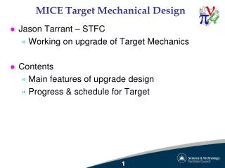
MICE Target Mechanism MICE CM 18 RAL June 2007 P J Smith University of Sheffield
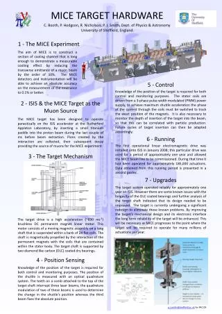
Target Progress Summary • Target Review - Decision to continue working with the present control system rather than design from new. • Target Acceleration has been increased and it is now able to get into and out of the ISIS beam in time. • Long term testing of both the hardware and control software is now underway. • Control software appears to be robust ->Testing has enabled minor issues to be resolved. • Target cooling appears adequate at the required acceleration. Actuator runs at about 65 deg C • Target Bearings are wearing out very quickly. We are currently in the process of trying to resolve this by looking at alternative bearing materials. • If we can solve the bearing issues then progress looks good for installation onto ISIS later this year
Target Review March 07 • A target review meeting was held at Daresbury Laboratories in March 2007 to look at whether a new control system was required. • It was agreed that designing a new system from scratch was not feasible in such a short period of time and so work would continue on improving the present design. • This was felt not to be without it risks… Disadvantages: • Significantly lower processing power by continuing to use an 8 bit controller • Not been able to implement various feedback algorithms which we feel would further stabilise the targets trajectory • We cannot use all of the positional resolution that we have available. This means we don’t have the degree of control that we would have liked
Reminder of Target Specifications: • ISIS runs at 50Hz ~10ms beam on and acceleration + 10ms beam off • We need to intersect the last ~2ms of a given ISIS pulse without causing beam loss at any other time • The target will run at 1Hz intercepting just 1 in 50 of the ISIS pulses • Last autumn we ran some tests at ISIS that allowed us to build a profile of how the beam radius alters with time at the target point in the vertical direction. • The original specification was to have the control over the position to which the target dips to within +-0.5mm
Required Target Trajectory ~80g Acceleration ~30ms Distance from beam centre mm BEAM RADIUS Time ms Target intercepts ISIS beam for ~2mS
Top Bearing Magnets Simplified Diagram of the Internal Mechanics Coils Water Cooling Bottom Bearing
Target Progress • Temperature Protection system put in place April 07 – This allows unsupervised 24/7 running • Power supply received from Daresbury - Tested at Daresbury up to 70 Amps - Theoretically it could deliver up to 80 Amps Note that we had previously only been able to deliver 10Amps to our actuator! • Started running at low currents for several hours at a time • Increased the coil currents as confidence with the system increased and problems were resolved. Running at 60 Amps coil current. (Will shortly show how that corresponds to acceleration and trajectory)
Target Reliability We have started some long term testing with the target, so what do we need to achieve? • Lifetime of about 6 months between replacements • Running at 1 Hz 8 hours per day: 5 million actuations 24 hours a day: 15 million actuations Long Term stability • How repeatable does the movement need to be? • What long term changes do we see? – mechanical • Reliability of control electronics and power supply
Target Progress • Using 2 shafts Light ~ 27 grams Cross Section Heavy ~ 35 grams Square Section • Each of these uses different bottom bearings (top bearings are interchangeable • Clearly we would like to use the lighter one as it gives a higher acceleration for a given coil current. This is the one that is designed for use in ISIS.
Target Drops & Control Reliability • The target is held out of the beam electromagnetically and so any problems with the control electronics can result in the target being dropped. • Result of a target drop is that the target will fall into the ISIS beam and the beam loss will trip ISIS off. • Clearly we would like this to happen as little as possible but it is a possibility that needs to be considered • The baseline that we have been given is that the target needs to be reliable enough so that it doesn’t drop more than once a day. ~ 1 in every 86400 pulses.
40 Amps ~59g 30 Amps ~43g 60 Amps ~85g 10 Amps ~15g 20 Amps ~31g Dip Depth Dip Time Acceleration Achieved – Heavy Shaft
Table to show the Number of Actuations Performed in the Testing as a Function of Actuator Current and how this Translates into Target Acceleration Note that target travel is 44mm And also note that dip time here refers to the time for the target to get from top to bottom (i.e. half of it’s trajectory)
Ignore! Dip depth was changed manually at the start of the run Gradual Drift over 250,000 pulses. Is this bearing wear? DAQ - What are we measuring? • The sorts of trends that we are looking for include: • Changes in dip depth over time • The spread in dip depth • The time it takes for the target to reach the required dip depth and how this changes over time • Changes in start position • This is still under development as it is only recently that we have acquired enough data to be able to start looking for ‘interesting’ things! • The following plots represent a run at 60A using the heavy shaft ~250K events. Please don’t read too much into these at the moment, they are provided as examples!
Target Reliability Two main problems: • Glitches in the electronics that caused the target to drop. Possible origins of the glitch? • Dust from bearing wear? • Electrical Noise - Poor Grounding, Poor Screening • Poor Connectors • The Glitching now appears to be a solved problem as shown on the next slide 2) Bearing Wear - Revisit in a couple of slides time
Target Reliability • Bearings – We were running on ceramic bearings • Photos on next slide– Wearing out in typically around 100,000 actuations • 3 possible elements to this problem • Is the Bearing material not suitable? – Ceramic material is relatively ‘soft’ • Is the shaft not straight? • Is there a radial force on the target shaft?
Target Reliability • Changed to Brass/Aluminium Bearings -> These appear to be wearing much better BUT brass is not an approved material for use in ISIS • PHOTOS are on the next slide • Square Section Shaft seems to run much truer than the cross section shaft. • Bearings wear more slowly using the Square (heavier) shaft • Have yet to address how much any off-axis force has to bear on this situation – Possible causes: • Coil misalignment – What are the acceptable tolerances? • Any off axis misalignment of the target with respect to the coils • These effects must be small • Awaiting some FE simulation results from our R.A. M. Mohammed
Target Reliability • Designing some bearing mounts that use ruby bearings. Hopefully these will be much more hard wearing. • Questions? • Why are the bearings wearing so quickly? • Is this a problem with the stator design? Off axis forces? • Is there a problem with the target shaft? Is it perfectly straight? • Will the new bearings actually eliminate the problem or will some wear still be expected and if so: • Will the production of dust from wear be an issue for use of the target in ISIS? We expect that we will always see some bearing wear and therefore there will always be some dust produced
Installation • Target electronics is being situated in the atrium outside of the synchrotron entrance. • Waiting for confirmation of cable run lengths • The original intention was to install onto ISIS in late June. Clearly with the problems that we’re having with the bearings this isn’t going to happen. • End of our window of opportunity for installation this summer is mid July 07. • This date looks tight but may be possible if we can solve the bearing wear problem quickly? • Next installation opportunity after this will be Christmas 07.
Remaining Work • Interfacing issues with ISIS & MICE needs to be looked at in further detail – This was started yesterday with the installation meeting. • Control Electronics crate needs rebuilding • Extra protection circuitry added to protect power amplifier • Delay circuits to interface with ISIS signals • Interlocks to prevent system changes without a physical key • Driver circuits for signalling • Power Supply for control electronics • Temperature monitoring for DAQ • Etc i.e. Much still to be done! (as is usual!!)
Conclusions • A Very Significant amount of progress has been made with the target. • The target is now Operating at the ‘specification’ acceleration. • We are working to improve the reliability of the mechanism to prevent target drops. Basically there. • Bearing Wear is probably now our single biggest concern. • We would like to have longer runs so that long term trends can be monitored more effectively on the DAQ (but we will need better bearings before we can do this!)
2 High Speed Photographs (10mS) taken of the target movement at 80g acceleration