Download
1 / 38
390 likes | 578 Views
Optical Fiber Communications: Even More Fun in the Post-Bubble Era. Joseph M. Kahn. Department of Electrical Engineering Stanford University www-ee.stanford.edu/~jmk. Clean Slate Seminar, February 6, 2006. Adaptive Signal Processing in Multimode Networks Elad Alon Shanhui Fan

E N D
Optical Fiber Communications:Even More Fun in the Post-Bubble Era Joseph M. Kahn Department of Electrical Engineering Stanford University www-ee.stanford.edu/~jmk Clean Slate Seminar, February 6, 2006
Adaptive Signal Processingin Multimode Networks Elad Alon Shanhui Fan Mark A. Horowitz Wei Mao Rahul A. Panicker Mahdieh B. Shemirani Xiling Shen Vladimir Stojanovic StrataLight Communications Keang-Po Ho Modulation and Detection in Single-Mode Networks Ezra Ip Alan P. T. Lau Dany-Sebastien Ly-Gagnon Jin Wang Acknowledgments
Optical Networks: Meter to Megameter Scale • Sensors • Local- and campus-area • Access • Metropolitan • Long-haul • Submarine
Optical Networks: Meter to Megameter Scale • Sensors • Local- and campus-area • Access • Metropolitan • Long-haul • Submarine
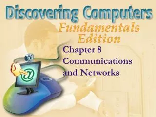
n 8-10 mm Single-mode n 50 mm Step-index multi-mode n 50 mm Graded-index multi-mode Optical Fiber Types • Wide-area, metro-area networks • Limitations: amplifier noise, fiber nonlinearity • Throughput (with WDM): 80 channels 40 Gb/s 4000 km • Local-area networks • Limitation: large modal dispersion • Throughput (without WDM): 100 Mb/s few km • Local-area, campus-area networks • Limitation: moderate modal dispersion • Throughput (without WDM): 1 Gb/s few km
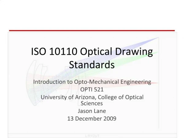
t Transmitted Received t Modes in Optical Fibers Modes • Mutually orthogonal solutions of wave equation having well-defined propagation constants. • Propagate without cross-coupling in ideal fiber. • Typical multimode fiber supports of order 100 modes. Modal coupling • Bends and imperfections couple modes over distances of the order of meters. • Coupling varies on time scale of seconds. Modal dispersion • Different modes have different group delays, causing pulse spreading.
Motivations • New techniques needed to: • Extend 10 Gb/s Ethernet over multimode fiber (currently limited to 300 m) • Enable 100 and 1000 Gb/s Ethernet over multimode fiber • Optical signal processing scales better than electronic signal processing to high bit rates, long fibers, multiple WDM channels. • Lesson from digital subscriber lines: ubiquitous, bandwidth-constrained media should be exploited to the limit. • Modal dispersion is analogous to multipath fading: should it beeliminated or exploited?
Principal Modes in Multimode Fibers • Multimode fiber • Supports 2N ideal modes (including 2 polarizations). • Ideal modes are strongly coupled by bends and imperfections. • Principal modes • PMs are linear combinations of ideal modes. • Input PMs: a set of 2N orthogonal modes at fiber input.Output PMs: a set of 2N orthogonal modes at fiber output. • Each input PM propagates to the corresponding output PM:Without cross-coupling to other PMs.With a well-defined group delay. • In a given fiber, the PMs change slowly over time.Adaptive signal processing can identify and track PMs. S. Fan and J. M. Kahn, Optics Letters, January 15, 2005.
« e ( x , y ) E ( k , k ) in , n in , n x y Controlling MMF Impulse Response via SLM • Input principal modes: • Mode incident on SLM: • SLM reflectance: • MMF impulse response:
desired bit interval undesired bit intervals System Model and Adaptive Algorithm • Continuous-time impulse response: • Discrete-time impulse response: • Objective function quantifying ISI: • Note that F(g(nT; t0)) > 0 when eye open and F(g(nT; t0)) <0 when eye closed. • Adaptive algorithm controls V(kx, ky) to maximize F(g(nT; t0)).
Experimental Setup X. Shen, J. M. Kahn and M. A. Horowitz, Optics Letters, November 15, 2005.
10 Gb/s 11081 m, Good SOP, Vertical Misaligment of Launch,Binary vs. Quaternary SLM
10 Gb/s 11081 m, Good SOP, Binary SLM,Tune Laser Over 600 GHz
Adaptive Spatial Optical Signal Processing • Key to exploiting principal modes. • Can be implemented using spatial light modulators. • One SLM can serve multiple WDM channels. • SLM requirements are at least somewhat independent ofbit rate and fiber length. • Contrast with electrical equalizers: • Must be implemented separately for each WDM channel. • FIR filter-based equalizers: number of taps proportional tobit rate fiber length. • Maximum-likelihood sequence detectors: number of states exponential in bit rate fiber length.
Ongoing and Future Work Ongoing • Modeling propagation and principal modes • Optimal one-shot and adaptive algorithms • Robustness to perturbations of fiber Future • What can we learn from adaptive systems to improve designof lower-complexity systems? • Extension to other multimode media, e.g., polymer waveguidesfor board-level interconnects • Electronics and optics for faster adaptation • Multi-input, multi-output transmission
Optical Networks: Meter to Megameter Scale • Sensors • Local- and campus-area • Access • Metropolitan • Long-haul • Submarine
Access Networks Technologies (Heterogeneity Rules) • Wireless (radio and microwave) • Free-space optical • DSL over copper twisted pair • QAM over hybrid fiber-coax (single-mode fiber) • TDM / WDM over passive optical networks (single-mode fiber) Some Issues • Performance vs. cost of installation and maintenance • Initial cost vs. upgradeability
Passive Optical Networks for Access • Downstream / upstream: 1.55 mm / 1.31 mm (coarse WDM) • Downstream: broadcast and select (TDM or TDM / WDM) • Upstream: TDMA multiple downstreamwavelengths (TDM / WDM) single downstreamwavelength (TDM)
Tx1 Rx1 f f f f1 fN f2 … f1 f1 Tx2 Rx2 f f f2 f2 Erbium-Doped Fiber Amps … … … … TxN RxN f f fN fN Mux Demux 4.4 THz 5.4 THz Dense Wavelength-Division-Multiplexing EDFA Bands
Metropolitan and Long-Haul Networks • Use single-mode fiber • Use electrical TDM (e.g., SONET) on WDM • Transmission • Maturing technology, challenging business • 10 Gb/s transceivers approaching commodity status • Unused (dark) fibers exist on many routes • Many underutilized systems exist, e.g., 10 Gb/s 80 wavelengths with only 10 wavelengths in use • Switching • Circuit switching: becoming more dynamic and flexible, for reprovisioning, survivability, etc. • Packet switching: infeasible for several reasons, especiallylack of scalable optical buffers
Router Router Chicago Cleveland New York Optical add-drop demultiplexer l1 Long-haul core Optical cross- connect Kansas City Phila- delphia Nashville l2 Router Metro ring Metro ring Router Router Metropolitan and Long-Haul Networkswith Wavelength Routing
Long-Haul Transmission: Trends Increasing per-channel bit rates • For a given capacity, reduces number of ports on routers andoptical switches. • Last generation: 10 Gb/s • New generation: 40 Gb/s • Goal (of some): 160 Gb/s Increasing capacity • Traffic continues to increase exponentially; capacity must increase,cost per bit must decrease. • EDFA bandwidth is limited, Raman amps are expensive. • Best solution is to increase spectral efficiency: • Last generation: 0.2 - 0.4 b/s/Hz • New generation: 0.8 b/s/Hz • Binary limit: 1 b/s/Hz • Non-binary limit: perhaps 3-5 b/s/Hz
Long-Haul Transmission: Challenges Increasing per-channel bit rates • Chromatic dispersion: • Polarization-mode dispersion: • Electronic circuits Increasing spectral efficiency • Crosstalk and distortion in muxes, demuxes, OADMs, OXCs • Requires higher signal-to-noise ratio, but transmitted power islimited by nonlinearities in fiber.
Approaches for 40 Gb/s Systems at 0.8 b/s/Hz Mainstream • Goal: maximize unrepeatered transmission distance (à la Qtera) • Use OOK or DPSK with RZ pulses (broader spectrum) • Achieves: > 2000 km, 3.2 Tb/s (C band), 6.4 Tb/s (C + L bands) • Higher cost: • Two-stage modulator, complex receiver (for DPSK) • Careful control of chromatic dispersion in transmission system • Requires specially designed transmission system
ES ES f t t fS Differ- ential Encoder Bits Laser fS … Clock fS T OpticalBPF 0 ESQ Elect.LPF i 1 0 1 0 -1 1 i ESI 0 1 RZ DPSK with Interferometric Detection
Approaches for 40 Gb/s Systems at 0.8 b/s/Hz Mainstream • Goal: maximize unrepeatered transmission distance (à la Qtera) • Use OOK or DPSK with RZ pulses (broader spectrum) • Achieves: > 2000 km, 3.2 Tb/s (C band), 6.4 Tb/s (C + L bands) • Higher cost: • Two-stage modulator, complex receiver (for DPSK) • Careful control of chromatic dispersion in transmission system • Requires specially designed transmission system StrataLight Communications (founded in June 2000) • Goal: minimize cost per Gb/s•km with sufficient unrepeatered distance • Use OOK with NRZ pulses and line coding (narrower spectrum) • Achieves: > 1200 km, 3.2 Tb/s (C band), 6.4 Tb/s (C + L bands) • Lower cost: • Simple modulator and receiver • Less careful control of chromatic dispersion in transmission system • Can retrofit to some underutilized 10 Gb/s transmission systems
fS f LineCoder fS Bits … fS ElectricalLPF i ES ES -1 0 1 t OpticalBPF Laser |ES|2 0 1 0 1 i 0 1 Line-Coded OOK with Direct Detection
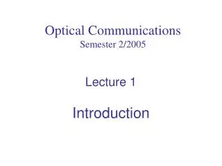
1 DF / pol. nb/neq Required for Pb = 10-9 (photons/bit) 2 DF / pol. 20 50 100 200 500 1000 2000 4 16 3 8 Number of Constellation Points M Relative Spectral Efficiency log2(M) (b/symbol) QAM / Coherent PSK / Coherent 2 4 DPSK / Interferometric or Diff. Coherent PAM / Director Non-Coherent 1 2 -3 0 3 6 9 12 15 SNR/bit Required Relative to 2-PAM (dB) Spectral Efficiency vs. SNR Efficiency
EI fS f fS Encoder Bits Laser EQ … f f 0 0 Elect.LPF iI 0 90 fL = fS 90 Elect.LPF iQ LOLaser Pol.Contr. Local Oscillator Photocurrent Signal ESQ ELQ iQ 01 00 01 00 ELI iI ESI 10 11 10 11 4-PSK with Coherent Detection Example: synchronous homodyne detection (optical phase-locked loop not shown) A. Porter and J. M. Kahn, 1992 S. Norimatsu et al, 1992
EI Encoder Bits Laser EQ … 90 Elect.LPF iI 0 90 Elect.LPF iQ Pol.Contr. LOLaser Signal Local Oscillator Photocurrent ESQ ELQ iQ 0000 0100 0100 1000 1100 1000 1100 0000 0001 0101 1001 0101 1101 0001 1101 1001 0111 0011 1011 0111 1111 1011 0011 1111 1110 0110 0010 1010 1010 1110 0110 0010 ELI iI ESI 16-QAM with Coherent Detection
Coherent Optical Detection: Pros and Cons Advantages • Yields 2 degrees of freedom: higher spectral efficiency • Receiver detects all information in signal electric field enables digital signal processing to compensate impairments • Chromatic dispersion • Polarization-mode dispersion • Nonlinear phase noise • Can use tunable local oscillator with electrical filtering to select channel enables fast-tunable receiver for wavelength switching (or FHSS) Drawbacks • Requires local oscillator laser at receiver • Requires polarization tracking or diversity at receiver
EQ EQ EI EI Nonlinear Regime Linear Regime Nonlinear Phase Noise
Optical Communication Research Issues Transmission • Higher spectral efficiency vs. wider utilized bandwidth • Spectral efficiency vs. robustness vs. implementation complexity • Signal processing: optical vs. analog vs. digital Switching • Circuit switching: faster and more flexible • Packet switching? Component evolution • New fiber types • New amplifier types • Optical buffers? Analysis • Spectral efficiency limits • Nonlinear phase noise
DARPA MTO TACOTA Program • Coherent links for tactical air-to-air communications • Major team: CeLight, Stanford (Fejer, Kahn), Boeing, HRL • Transmit at 3.8 mm to minimize atmospheric effects • 1.55 mm transmitters and receivers • Transmitter: 1.55 3.8 mm downconverter • Receiver: 3.8 1.55 mm upconverter • Use frequency hopping for LPI/LPD • Receiver architecture • Homodyne (direct conversion to baseband) • Use sampling and DSP algorithms to compensate carrier phase, Doppler shifts, atmospheric turbulence, etc.