Programming Microcontroller UART – Universal Asynchronous Receiver Transmitter 2007
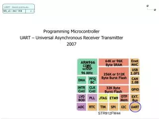
Programming Microcontroller UART – Universal Asynchronous Receiver Transmitter 2007. 64K or 96K Byte SRAM. Enet MAC. ARM966E. CORE. w/DSP. USB 2.0FS. 96 MHz. 256K or 512K Byte Burst Flash. PFQ BC. CAN 2.0B. DMA. INTR Cntl. CLK Cntl. 32K Byte Burst Flash. GPIO.

Programming Microcontroller UART – Universal Asynchronous Receiver Transmitter 2007
E N D
Presentation Transcript
Programming Microcontroller UART – Universal Asynchronous Receiver Transmitter 2007 64K or 96K Byte SRAM Enet MAC ARM966E CORE w/DSP USB 2.0FS 96 MHz 256K or 512K Byte Burst Flash PFQ BC CAN 2.0B DMA INTR Cntl CLK Cntl 32K Byte Burst Flash GPIO OTP Mem LVD BOD EXT. Bus JTAG ETM9 PLL RTC TIM ADC SPI I2C UART UART - Serial communic. STR912FW44
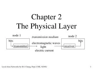
Typical serial communication(low level) UART - Serial communic. Full-duplex interface Device 1 Receive Transmit Device 2 Transmit Receive -PC -embedded system -modem -barcode reader -printer -display (with terminal emulation software) -data logger -sensor (simple or complex) -dongle (security element) -I/O module (digital, analog, encoder, PT100) -wireless interface • PC • Embedded system
EIA-232-C pin assignmentsD-Sub male on PC UART - Serial communic. Male -> Stecker Female -> Buchse RS-232-C: Radio Sector, American Standard since 1969s
Serial data format(logical representation) UART - Serial communic. 1-2 stop bits msb lsb 1 5-8 data bits 0 n Parity bit if enabled start time lsb: least significant bit (20) msb: most significant bit (2 db-1) Normally one Byte is sent as 8 data bits Or: One Byte is sent as 7 data bits + parity 1 bit time = 1 / baudrate Example: parity enabled, 2 stop bits
Hyperterminal usage UART - Serial communic. Start -> Zubehör -> Kommunikation -> Hyperterminal Go offline Configure COM-Port: File->Properties Xon/Xoff: Software handshake (Exchange on..) <ctrl-q>/<ctrl-s> both sides must implement this software handshake. The sender has to stop almost immediately upon reception of Xoff character Binary data transmission is not possible. Hardware: RTS/CTS hardware handshake garantees loss-free transmission on a byte level and allows binary data transmission
Hyperterminal communication(no handshake) UART - Serial communic. a) Reset the controller. It will send a string b) Now type some characters. The controller will echo them (not hyperterminal!) try BS character (<ctrl-H> backspace) The terminal will interprete it properly try LF character (<ctrl-J> line feed, 0x0D). The cursor will move one line down try CR charcter (<ctrl-M> carriage return, 0x0A). The cursor jumps to column 0 Serial ports may be simulated using the Simulator output and the serial window: View -> Serial Window -> UART #0
Simple serial communication (3-wire) Multiple physical interfaces: EIA-232 Peer-to-peer (former RS-232-C 1969). Gnd based (-15..-3,3..15 V) EIA-485 Party Line, multi-point link (SCSI, ISDN, ... EIA-422 : Balanced lines, no ground link (D+/D-) on drivers up to 1'000m @ 100 kbps. Point-to-point or multi-drop. 0-5 V. Twisted-pair cable Easy setup Direct programming Byte level only USB will not replace cheap and simple communications UART – What is it good for? UART - Serial communic. EIA: Electronic Industry Alliance
Hardware flow control UART - Serial communic. RTS will be switched on and off by programmable receiv FIFO watermarks
Separate 16x8 Transmit and 16x12 Receive FIFO Programmable FIFO disabling for 1-byte depth Programmable Baud rate generator : Baud rate = UARTCLK / (16 × BRR) Standard Asynchronous communication bits (start, stop and parity) Independent masking of transmit FIFO, receive FIFO, receive timout, modem status, and error condition interrupts False start bit detection Line Break Generation and Detection Support for Modem Control Functions CTS, DCD, DSR, RTS, DTR, and RI Programmable hardware flow control UART features (1/3) UART - Serial communic. FIFO: First In First Out sequential, buffer structure
Programmable word length : 5 bits, 6 bits, 7 bits, 8 bits Programmable Stop bits : 1 Stop bit, 2 Stop bits Even, odd, stick, or no-parity bit generation and detection Support for Direct Memory Access (DMA) Support for an IrDA Serial Interface (SIR) protocol EnDec Parity control Loop Back Support baud rates of up to 460.8 Kbits / second subject to UARTCLK reference clock frequency UART features (2/3) UART - Serial communic.
11 Interrupt sources : Overrun error detected Break Error Parity Error Framing Error Receive Timeout Data Transmit Data Receive Modem Data Set Ready (DSRMIM) Modem Data Carrier Detect (DCD) Modem Clear to Send (CTS) Modem Ring Indicator (RI) UART features (3/3) UART - Serial communic.
UART Block diagram UART - Serial communic. Ref manual figure 74
UART register map UART - Serial communic.
Fractional Baud Rate generator UART - Serial communic. Every baud rate generator has errors. Check the tolerance! BRCLK: baud rate clock
UART configuration UART - Serial communic. [Peripherals -> UART]
P3.0 UART0_RxD Alternate Input 1 P3.1 UART0_TxD Alternate Output 2 Pin connections of UART UART - Serial communic. Use COM1 of MCBSTR9. Which port? STR91x ARM966 manual 12274.pdf, 4.1 pin functions page 36