Chapter 2 The Physical Layer
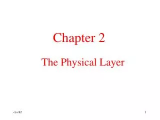
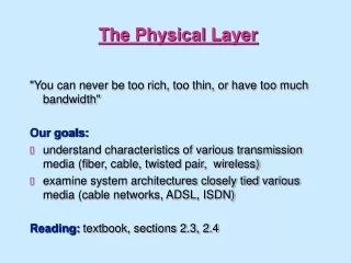
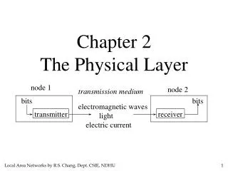
Chapter 2 The Physical Layer. node 1. node 2. transmission medium. bits. bits. electromagnetic waves light electric current. transmitter. receiver. 2.1 The Theoretical Basis for Data Communication.

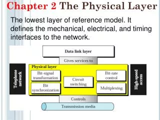
Chapter 2 The Physical Layer
E N D
Presentation Transcript
Chapter 2 The Physical Layer node 1 node 2 transmission medium bits bits electromagnetic waves light electric current transmitter receiver
2.1 The Theoretical Basis for Data Communication Information can be transmitted on wires by varying some physical property such as voltage or current. By representing the value of this voltage or current as a single-valued function of time, f(t), we can model the behavior of the signal and analyze it mathematically. 2.1.1 Fourier Analysis Any reasonably behaved periodic function, g(t), with period T can be constructed by summing a (possibly infinite) number of sines and cosines: where f=1/T is the fundamental frequency and an and bn are the sine and cosine amplitudes of the nth harmonics.
2.1 The Theoretical Basis for Data Communication 2.1.1 Fourier Analysis Root mean square amplitude
2.1 The Theoretical Basis for Data Communication 2.1.2 Bandwidth-Limited Signals ASCII character “b” A binary signal to be transmitted
2.1 The Theoretical Basis for Data Communication 2.1.2 Bandwidth-Limited Signals One harmonic Two harmonics
2.1 The Theoretical Basis for Data Communication 2.1.2 Bandwidth-Limited Signals Four harmonics Eight harmonics
2.1 The Theoretical Basis for Data Communication 2.1.2 Bandwidth-Limited Signals No transmission facility can transmit signals without losing some power in the process. If all the Fourier components were equally diminished, the resulting signal would be reduced in amplitude but not distorted. Unfortunately, all transmission facilities diminish different Fourier components by different amounts, thus introducing distortions. Usually, the amplitudes are transmitted undiminished from 0 up to some frequency fc [cycles/sec=Hertz(Hz)} with all frequencies above the cutoff frequency strongly attenuated.
2.1 The Theoretical Basis for Data Communication 2.1.2 Bandwidth-Limited Signals The width of frequency range transmitted without being strongly attenuated is called the bandwidth. 例如對某一種介質,若其cutoff frequency在n=8,則在此介質 最好的波形即為: Eight harmonics
2.1 The Theoretical Basis for Data Communication 2.1.2 Bandwidth-Limited Signals How many harmonics are needed? For digital transmission, the goal is to receive a signal with just enough fidelity to reconstruct the sequence of bits that was sent. It is wasteful to use more harmonics to receive a more accurate replica.
2.1 The Theoretical Basis for Data Communication 2.1.2 Bandwidth-Limited Signals Frequency Spectrum 0Hz 20Mhz 40Mhz 60Mhz … Baseband: Signals that run from 0 up to a maximum frequency are called baseband signals. Passband: Signals that are shifted to occupy a higher range of frequencies are called passband signals.
2.1 The Theoretical Basis for Data Communication 2.1.2 Bandwidth-Limited Signals The time T required to transmit the character depends on both the encoding method and the signaling speed [the number of times per second that the signal changes its value]. The number of changes per second is measured in baud. Bit rate=(baud rate)*log2(# of signal levels) 0 or 1
2.1 The Theoretical Basis for Data Communication 2.1.2 Bandwidth-Limited Signals Given a bit rate of b bits/sec, the time required to send 8 bits is 8/b, so the frequency of the first harmonic is b/8 Hz. An ordinary telephone line, often called a voice-grade line, has an artificially introduced cutoff frequency just above 3000Hz. This restriction means that the number of the highest harmonic passed through is 3000/(b/8) or 24000/b roughly.
2.1 The Theoretical Basis for Data Communication 2.1.2 Bandwidth-Limited Signals
2.1 The Theoretical Basis for Data Communication 2.1.2 Bandwidth-Limited Signals Analog bandwidth (measured in Hz) Digital bandwidth (measured in bit/s)
2.1 The Theoretical Basis for Data Communication 2.1.3 The Maximum Data Rate of a Channel Nyquist’s Theorem for noiseless channel Maximum date rate=2Blog2Vbits/sec bandwidth number of signal levels For example, a noiseless 3-kHz channel cannot transmit binary signals at a rate exceeding 6000 bps.
2.1 The Theoretical Basis for Data Communication 2.1.3 The Maximum Data Rate of a Channel If random noise is present, the situation deteriorates rapidly. The amount of thermal noise present is measured by the ratio of the signal power to the noise power, called the SNR (signal-to-noise ratio)(S/N). Usually, the ratio itself is not quoted; instead, the quantity 10 log10S/N is given. These units are called decibels (dB). Shannon’s Theorem Maximum number of bits/sec=Hlog2(1+S/N) For telephone line: 3000log2(1+30dB)30000bps. For ADSL (Asymmetric Digital Subscriber Line: (1M)log2(1+40dB)13Mbps.
2. Physical Layer 2.2 Guided Transmission Media 2.2.1 Magnetic Media A tape can hold 800 gigabytes. A box can hold about 1000 tapes. Assume a box can be delivered in 24 hours. The effective bandwidth=800*1000*8/86400=70Gbps Never underestimate the bandwidth of a station wagon full of tapes hurtling down the highway.
2. Physical Layer 2.2 Transmission Media 2.2.2 Twisted Pair Although the bandwidth characteristics of magnetic tape are excellent, the delay characteristics are poor. Twisted Pair: used in local loop in telephone systems The purpose of twisting the wires is to reduced electrical interference from similar pairs close by.
2. Physical Layer 2.2 Transmission Media 2.2.2 Twisted Pair A signal is usually carried as the difference in voltage between the two wires in the pair. This provides better immunity to external noise because the noise tends to affect both wires the same, leaving the differential unchanged.
2. Physical Layer 2.2 Transmission Media 100Mbps Ethernet 2.2.2 Twisted Pair 1Gbps Ethernet Category 5 UTP cable with four twisted pairs
2. Physical Layer 2.2 Transmission Media 2.2.2 Twisted Pair Unshielded Twisted Pair (UTP) More twists per centimeter, less crosstalk (a) Category 3 UTP (b) Category 5 UTP
2. Physical Layer 2.2 Transmission Media 2.2.2 Twisted Pair Simplex Half-duplex Full-duplex
2. Physical Layer 2.2 Transmission Media 2.2.3 Coaxial Cable (coax, co-ax) A coaxial cable Use digital transmission. For 1-km cables, a data rate of 1 to 2 Gbps is feasible.
2. Physical Layer 2.2 Transmission Media 2.2.4 Power Lines A network that uses household electrical wiring.
2. Physical Layer 2.2 Transmission Media 2.2.4 Power Lines The difficulty with using household electrical wiring for a network is that it was designed to distribute power signals, a 50-60 Hz signal. The wire attenuates the much higher frequency (MHz) signals needed for high-rate data communication. Noises when appliances are turned on or off Under development and standardization
2. Physical Layer 2.2 Transmission Media 2.2.5 Fiber Optics Computing speed: a factor of 16 improvement per decade, but near limit Communication speed improvement: also close to a factor of 16, but unbounded improvement possible In the race between computing and communication, communication won. The new conventional wisdom should be that all computers are hopelessly slow, and networks should try to avoid computation at all costs, no matter how much bandwidth that wastes.
2. Physical Layer 2.2 Transmission Media 2.2.5 Fiber Optics Computing a bit is cheaper (use less energy) than moving a bit. Moving electricity is more expensive than moving bits. So Google and the like move huge amounts of data across the network to where it is cheaper to store and compute.
2. Physical Layer 2.2 Transmission Media 2.2.5 Fiber Optics An optical transmission system has three components: the light source, the transmission medium, and the detector. Light source: LED (Light Emitting Diode) or Laser (Light Amplification by Simulated Emission of Radiation) Transmission Media: ultra-thin fiber of glass Detector: using light-electricity effect, generate an electrical pulse when light falls on it
2. Physical Layer 2.2 Transmission Media 2.2.5 Fiber Optics A comparison of semiconductor diodes and LEDs as light sources
2. Physical Layer 2.2 Transmission Media 2.2.5 Fiber Optics How to avoid light leaking when transmitting in glass? • Signal propagates in different material (air, cable, or fiber, etc.). • speed in dielectric is less that in vacuum • signal energy is absorbed in dielectric speed of light in vacuum propagation speed in dielectric material= refraction index
2. Physical Layer 2.2 Transmission Media 2.2.5 Fiber Optics refraction and reflection incident ray reflected ray refracted ray
2. Physical Layer 2.2 Transmission Media 2.2.5 Fiber Optics perpendicular light partially reflected total reflection critical angle q a
2. Physical Layer 2.2 Transmission Media 2.2.5 Fiber Optics refraction and reflection In time t, one light goes from A to B, another from C to D. Therefore, d2 D C b B a d1 A Snell's Law Total reflection
2. Physical Layer 2.2 Transmission Media 2.2.5 Fiber Optics Total reflection critical angle q Medium 1 Medium 2 a Remember: Total reflection only occurs when light goes from large index to small index.
2. Physical Layer 2.2 Transmission Media 2.2.5 Fiber Optics (a) Three examples of a light ray from inside a silica fiber impinging on the air/silica boundary at different angles. (b) Light trapped by total internal reflection.
2. Physical Layer 2.2 Transmission Media 2.2.5 Fiber Optics Multimode fiber cross section core cladding protective coating two propagation modes >
2.2 Transmission Media 2.2.5 Fiber Optics Multimode fiber
2. Physical Layer 2.2 Transmission Media 2.2.5 Fiber Optics Multimode fiber As a pulse of light travels through the fiber, the pulse of light spreads out This phenomenon is known as dispersion. Chromatic dispersion input pulse output pulse
2. Physical Layer 2.2 Transmission Media 2.2.5 Fiber Optics Multimode fiber Dispersion limits the achievable bit rate over a fiber of a given length. Conversely, given a bit rate, dispersion limits how long the link can be. spread-out will cause interference.
2. Physical Layer 2.2 Transmission Media 2.2.5 Fiber Optics Multimode fiber Why does fiber have more bandwidth than coaxial cable? Bits are more crowded, not faster. One second
2. Physical Layer 2.2 Transmission Media 2.2.5 Fiber Optics Multimode fiber To avoid interference, one must either lengthen the interval between bits (reducing the signaling rate) or shorten the fiber by inserting some type of communication device that restores a clean pulse. more components more expensive and less reliable
2. Physical Layer 2.2 Transmission Media 2.2.5 Fiber Optics Single-mode fiber If the fiber’s diameter is reduced to a few wavelengths of light, the fiber acts like a wave guide, and the light can only propagate in a straight line, without bouncing, yielding a single-mode fiber. Single-mode fibers are more expensive but can be used for longer distances and have larger data rates (since it has no dispersion).
2. Physical Layer 2.2 Transmission Media 2.2.5 Fiber Optics Attenuation in decibels = 10log10(transmitted_power/ received_power) Infrared region
2. Physical Layer 2.2 Transmission Media 2.2.5 Fiber Optics Three wavelength bands are used for communication. They are centered at 0.85, 1.30, and 1.55 microns, respectively. The latter two have good attenuation properties (less than 5% loss per kilometer). The 0.85 micron band has higher attenuation, but the nice property that at that wavelength, the lasers and electronics can be made from the same material (gallium arsenide). All three bands are 25,000 to 30,000 GHz wide. Ex1: Find out why.
2. Physical Layer 2.2 Transmission Media 2.2.5 Fiber Optics A fiber optic ring with active repeaters Can have many nodes and the link can be kilometers long.
2.1 The Theoretical Basis for Data Communication 2.2 Transmission Media A passive star fiber network 2.2.5 Fiber Optics # of nodes limited by the sensitivity of the photodiodes
2. Physical Layer 2.2 Transmission Media 2.2.5 Fiber Optics Comparison of fiber optics and copper wire advantages Fiber Copper Higher bandwidth 50km per repeater 5km per repeater less interference thin and light weight quite difficult to tap a familiar technology cheaper interface bi-directional
2. Physical Layer 2.2 Transmission Media 2.2.5 Fiber Optics
2. Physical Layer 2.3 Wireless Transmission 2.3.1 The Electromagnetic Spectrum Electromagnetic Waves one cycle speed=frequency wavelength m/s=cycles/s m/cycles Hz(hertz) speed of light (in vacuum)=
2. Physical Layer 2.3 Wireless Transmission 2.3.1 The Electromagnetic Spectrum