Download
1 / 48
500 likes | 684 Views
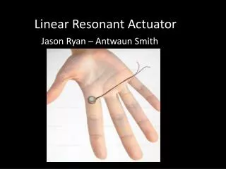
CONTROL OF THE HYBRID SOLID-STATE AND ELECTRIC LINEAR ACTUATOR. Musoke H. Sendaula and Saroj K. Biswas Temple University, Electrical and Computer Engineering Department, Joseph P. Teter 1 and Dave Brady 2 Naval Surface Warfare Center, Carderock Div 1 Materials Science Branch (C/645)

E N D
CONTROL OF THE HYBRID SOLID-STATE AND ELECTRIC LINEAR ACTUATOR Musoke H. Sendaula and Saroj K. Biswas Temple University, Electrical and Computer Engineering Department, Joseph P. Teter1 and Dave Brady2 Naval Surface Warfare Center, Carderock Div 1Materials Science Branch (C/645) 2Integrated Weapons/Cargo Handling Systems Branch (C/977) American Control Conference, June 30 – July 2, 2004
Hybrid Solid-state and Electric Actuator Development Program Base Period Project Objectives and Tasks. Magnetostrictive Solid-state Thrusters Background Hybrid Linear Actuator (HLA) for the Flush Deck Hatch Design Development of the Control System for the the Flush Deck Hatch HLA. Presentation Outline
Objective: Develop a power dense electric actuator for use in strike up/down weapons & cargo handling. Innovation: Implement magnetostrictive thrusters for high linear power actuation coupled with medium power linear motors for ancillary service. Application: Replace high thrust hydraulic actuatorsto reduce dependence on electro-hydraulic power transmission. Hybrid Linear Actuator Development Program Project Objectives.
Hybrid Linear Actuator Development Program Project Tasks and Results. • Tasks and results: • Identified particular hydraulic actuator to replace. CVN68 Class weapons elevators utilize hydraulic actuators for hatch and door operation. The flush deck hatch actuators have the greatest thrust demand and were therefore targeted for replacement. • Estimation of the thrust capacity needed for the flush deck hatch in adverse ship motion (sea state 5) with adverse climatic condition (wind and ice load). Identified power requirement to meet current hatch speed during operation.
Hybrid Linear Actuator Development Program Project Tasks and Results. • Tasks and Results(Cont’d): • Established the HLA physical parameters of size, shape, stroke length, mounting configuration, etc. for direct replacement to support future transition plan. • Developed and reviewed several conceptualizations HLA designs. • Studied thermal management requirement based on power requirements and anticipated heat dissipation. • Designed and evaluated several clutch/brake concepts. • This paper focuses on the HLA Controller design.
HLA Target Application CVN Flush Deck Hatch (Flight Deck or Main Deck) 10’ x 20’ HY-100 Hatch weighs approximately 19,000 lbs.
HLA Target Application Details Existing Hatch Hydraulic Actuators (2) Installed in Recessed Pockets
HLA Target Application Details Major Components of Existing CVN Hydraulic Power Unit (6) 6 cu.ft. HP gas flasks 100 Gallon Head Tank Welded steel piping (P1) (2) 50 HP motors w/controllers (2) 53 GPM pumps 10 Gallon control accumulator (6) 25 Gallon Piston Accumulators Oil/Sea Water Heat Exchanger Cooling Pump w/motor and controller
HLA Target Application Advantages TOC SUMMARY (SINGLE SHIP) Hydraulic System Electro-Mechanical Magnetostrictive System Acquisition $3.76 M $2.69 M $1.41 M DAOOC $3.51 M $1.57 M $957 K Total 1998 ($) $7.27 M $4.26 M $2.37 M (DAOOC - Discounted Annual Operations and Overhaul Costs)
Magnetostrictive Solid-State Thruster Background Terfenol-D with axial bore
Magnetostrictive Solid-State Thruster Background Magnetic Field l l + D l Magnetostriction
Magnetostrictive Solid-State Thruster Physical Mechanism H H DS DS No field, no stress; rod is partially elongated. Field applied, rod elongated. No field, stress applied; rod compressed. Field and stress applied, elongating rod.
MAGNETOSTRICTION COUPLING EQUATIONS In magnetostrictive materials, the mechanical and electrical properties are coupled: Stress (mechanical) Field (magnetic) Strain (mechanical) Flux (Magnetic) where S is the strain, T is the stress, H is the applied field, B is the magnetic flux density and s (the compliance), d (the piezo-magnetic constant) and m (the permeability) are material constants; d defines the coupling between magnetic and mechanical properties. With these definitions, the coupling factor k, which describes the energy transfer between the mechanical and magnetic systems, is:
Magnetostrictive Solid-State Thruster Advantages • Robust • No aging mechanism • No properly mounted and operated sample has been known to fail. “Properly mounted and operated” means kept under compression. (The material is brittle and an unmounted specimen might break if dropped or placed under tension.) • Inadvertent operation at high temperature reduces the available strain, but causes no permanent change in the material. It regains its original properties when the temperature drops. • Low Voltage Operation • Used in a prototype diver communication system • High Power Density • Ten times power density of nearest competitive technology NSWCCD Magnetic Materials Group, Code 645
Magnetostrictive Success Story NUWC / SANDERS TERFENOL “DOGBONE” FLEXTENSIONAL 930 Hz, 212 dB SANDERS MODEL 30 PZT FLEXTENSIONAL 1030 Hz, 207.5 dB BAeSEMA PZT FLEXTENSIONAL 813 Hz, 206 dB Photograph from NUWC, Newport The Terfenol dogbone flextensional SONAR projector delivers 3 times the acoustic power with 1/3 the weight and considerably less volume of a comparable pzt flextensional (model 30)
HLA Operation Details • Basic Operation: • The HLA is designed to “inch worm” at a high frequency to result in a smooth linear motion over the 36” of stroke travel. • Magnetostrictive actuators will generate extremely high axial force when energized but will only extend their basic length by 2 mils per inch of length. • The current design of the HLA will thrust 24 mils per cycle. • The HLA will have two stages, each thrusting equally but timed phased to cut the excitation frequency in half. • The mechanical clutches will transmit thrust to the actuator shaft and will be reset by the linear motors for the next power cycle.
Flush Deck Hatch HLA Control System Design • Control Problem: • Design a controller for the HLA to open and close the Flush deck Hatch during high sea states • The control system should be able to operate in the presence of wind loads and ship motion
Flush Deck Hatch HLA Control Systems Dimensions All dimensions are in meters
Flush Deck Hatch HLA Control System Dimensions at Opening All dimensions are in meters
Modeling of Flush Deck Hatch Hatch is modeled as a rotating plate = Hatch Angular position WL = wind load Fd = Drive force g = acceleration due to gravity Mh = Mass of the Hatch Iz = Moment of inertia of hatch
Modeling of Windload Angle of attack
Modeling of Windload Force applied to hatch due to deck wind = wind speed = angle of attack = wind direction factor, = +1 if wind assists opening of hatch = -1 if wind obstructs opening of hatch = lift coefficient
Modeling of Windload Wind speed and direction are random = mean wind speed = hatch angle , = random processes
Effects of Sea state Ship oscillations • change the angle of attack • apply an inertial force on the hatch as it rotates = = random process
Effective Load due to Deck wind and Sea state Combining the wind load and the effects of sea state, and after some simplification = covariance of wind noise process = equivalent random noise process
Normalized Model Equation is normalizedwith respect to weight of the hatch
Normalized Model = Normalized wind load A highly nonlinear stochastic model
Feedback Linearization If the actuating force Fa , the HLA drive force is taken as = control signal for the linearized system The simplified equation is obtained as
Trajectory Following Control Desired hatch opening trajectory for the nominal system = time to open the hatch Desired nominal trajectory following control
Trajectory Following Drive Force Total nominal trajectory following drive force for the mean dynamics
Controller for Perturbed System The feedback linearized system is given by Because of the noise, the actual hatch opening trajectory will not follow the desired trajectory. Additional error correction is necessary.
Error Correcting Controller The controller is synthesized in two parts: • a feedback linearizing component • an error correcting component
Error Dynamics • Integral of position error • Position error • Velocity error Error Dynamics
Error Correcting Controller Consider a simple PID controller Using standard design method
Hatch OperationWindload assisting opening • Hatch Opening
Hatch OperationWindload assisting opening • Shaft Extension
Hatch OperationWindload assisting opening • Drive Force
Hatch OperationWindload obstructing opening • Hatch Angle
Hatch OperationWindload obstructing opening • Shaft Extension
Hatch OperationWindload obstructing opening • Drive Force
Effect of Wind Direction • Drive Force
Effect of Wind Speed • Drive Force
HLA Controller: Sensing and Implementation • Sensing will include: • HLA shaft extension (used to estimate hatch position) • HLA Shaft speed (used to estimate hatch speed) • Force at the HLA shaft and hatch hinges pins ( used to estimate wind and ship motion loads)
HLA Controller: Sensing and Implementation • The actuating force generated by the the magnetostrictive thrusters and the linear motors to the excitation currents. • Control signals will include commands to generate excitation currents for the multi-phase magnetostrictive thrusters, high force electric linear motors ,and the self-locking, magnetically activated clutches.