Download
1 / 46
530 likes | 1.1k Views
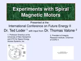
Experiments with Spiral Magnetic Motors. Presented at the: International Conference on Future Energy II. Dr. Ted Loder 1 with input from Dr. Thomas Valone 2. 1. Professor Emeritus at the University of New Hampshire and CTO for Space Energy Access Systems, Inc.

E N D
Experiments with Spiral Magnetic Motors Presented at the:International Conference on Future Energy II Dr. Ted Loder 1with input from Dr. Thomas Valone 2 1. Professor Emeritus at the University of New Hampshire and CTO for Space Energy Access Systems, Inc. 2. President of Integrity Research Institute, Chairman of COFE II
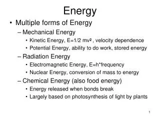
Magnets, created by spinning electrons, are used to perform useful work in motors and generators every day. The magnetic gradient (dB/dx) or changing magnetic field is known from classical physics to create a force in one direction, similar to but better than a linear motor.
Example of a Linear Magnetic Device Bearden, Thomas. 2002. Energy from the Vacuum. 952 pp. Cheniere Press, Santa Barbara, CA
Inhomogeneous Magnetic Fields Top View The net Force created on the ball bearing = the magnetic field gradient multiplied by the induced magnetic moment, as with the Stern-Gerlach Experiment --Modern Physics, Schaumm’s Outline Series, Gautreau et al., McGraw Hill, 1978 z Their experimental setup: The magnetic field B is more intense near the pointed surface at the top than near the flat surface below, creating a slope in a graph of B vs. z , which is the gradient dB/dz. Hartman Patent #4,215,330 Fz drop-off Side View 10 degree incline Steel ball bearing #4
Scott, David. Magnetic “Wankel” for electric cars. Popular Science, June 1979 pp. 80-81.
Spiral Magnetic ‘Wankel’ Uses Less Current than Conventional Motors even with a coil actuator.“In this time of uncertain gas supplies, electric cars look increasingly attractive.” Scott, David. Magnetic “Wankel” for electric cars. Popular Science, June 1979 pp. 80-81.
Spiral Magnetostatic MotorUtilizes Magnetic Gradient Electromagnetic coil wastes energy and heat • Magnetic rotor repelled from spiral Stator Magnet causingTorque • Light Sensor triggers the electromagnet to fire giving off a Magnetic Pulse • Pulsesends the Rotor Magnet past the magnetic field gap • Magnetic Gradient also used in the Stern-Gerlach physics experiment F Inhomogeneous magnetic fields (dB/dθ) create the circumferential force (F) Scott, David. Magnetic “Wankel” for electric cars. Popular Science, June 1979 pp. 80-81.
Kure Tekkosho Patents Inventors: Kuroda Takeshi, Ono Gunji, Sagami Eiji 1980 JP 55144783 Permanent Magnet Prime Mover JP 55114172 Electromagnetic Drive Machine JP 55061273 Rotary Power Generator JP 55053160 Magnetic Motive Power Machine JP55061274 & JP55136867 Magnetic Power Machine JP 55115641 Flywheel Utilizing Magnetic Force JP 55111654 Electromagnetic Power Unit JP 55106084 Magnetic Drive Machine JP 55071185 Magnetic Power Generator JP 55053170 Power Machine by Use of Magnetic Force
Coefficient of Performance - COP Coefficient of performance is an energy transfer term that defines the measure of output power divided by the operator’s input power. COP is used to describe any machinery that has additional energy input from the environment. Unlike the term “efficiency”, the COP defined above can be greater than one. COP is usually greater than efficiency, but will be equal to efficiency if the environmental energy input is zero. Energy flow for machines described by COP From: M. Walters M.R. Zolgahdri, A. Ahmidouch, A. Homaifar. Introducing the Practice of Asymmetrical Regauging to Increase the Coefficient of Performance of Electromechanical Systems.
The Problem • In the previously built spiral magnetic motors, electrical power must be input to the system to create a switched magnetic pulse. This pulse is needed to help the rotor traverse the gap (detent) between the end of the magnetic stator arc and the beginning of the stator spiral. Hence the term: ESLIM (Electromagnetically-Stimulated Linear Induction Motor). • With both a linear version and a spiral version, the conservation of energy needs to be stated again: • Valone’s Rule #1: Electric input energy, or its substitute, is always necessary with a basic Archimedean spiral magnetic gradient motor.
The Problem, cont. • The input energy is needed because of the powerful end effect which tends to pull the rotor backwards or repel the rotor as it reaches the detent region. • In summary, no matter what the speed of the rotor in a ESLIM design configuration, the end effect will either pull or repel the rotor with the same force the rotor accumulated during its circuit, thereby satisfying the conservation of energy. • Thus a more creative approach is necessary to transform the motor into a Magnetic Linear Induction Motor (MLIM), which can be configured either in a linear or spiral manner.
Computer model of magnetic fields for a conceptual MLIM Blue - Rotor magnets, Red - Stator magnets, Green - GMM-PZT, Yellow - Weigand switch for MR-PZT The principle of a magnetic gradient force is converted from the linear case to dB/dθ in the circular case. The radial magnetic field increases its attraction as the rotor turns through one complete cycle. (Valone, 2005) Note that this model is designed in the attractive mode.
Spiral Motors, a very short history Before we look further at the problem, let us look at several examples of spiral motor that have been built.
Kure Tekkosho, A Japanese firm Scott, David. Magnetic “Wankel” for electric cars. Popular Science, June 1979 pp. 80-81.
Magnetic “Wankel” motor built by Paul Monus inspired by the Japanese firm of Kure Tekkosho. Not OU but used only 80 mW to turn at 1400 rpm. Paul Monus (1982), "Permanent Magnet Motors --- Build One"
Spiraled Rotor Magnets Motor • Notes: • Magnets are on the rotor (c) • Motor is in attraction mode • Rotor has counterweight (9) • Magnets on steel shield (5) • Starts at x opposite stator 3 • Between magnet distances decrease from 2a to 2w • Magnet 2x helps reset • Will run 10-11 revolutions so not a free energy device From Leonard Belfroy’s site: http://www.spots.ab.ca/~belfroy/magnetmotors/spiraledRotorMotor.html
Working Replication of a Magnetic Wankel Motor Note: This motor is not OU but just demonstrates the spiral principle. http://www.cheniere.org/misc/wankel.htm
Paul Sprain Patent #6954019 (2005) Apparatus and process for generating energy
Paul Sprain’s Spiral Motor Picture Courtesy of Tom Valone
The Problem*, Solution 1 • The purpose of spiral arrangement is to confine the back EMF to a single portion of the motor. As the rotor enters the spiral detent or gap, it must be suddenly gauged asymmetrically to a magnetostatic scalar potential equal to or greater than the potential at the other end of the spiral gap where the magnetic gap is smallest. (Bearden, www.cheniere.org) • In other words, the rotor magnet has to be given a “kick” to get by the last magnet (or first magnet) to restart the spiral, this takes energy. * Remember Valone’s Rule #1
Study Aid Valone’s Rule #1: Electric input energy, or its substitute, is always necessary with a basic Archimedean spiral magnetic gradient motor.* * Don’t forget Valone’s Rule #1
The Problem, Solution 1 This sudden increase in the magnetostatic potential (asymmetric regauging) can be accomplished in the following manner: During the time the stator is rotating, a trickle current is maintained, at a small voltage, through the coil of the electromagnet. Just as the rotor enters the spiral gap, a sensor indicates its position and causes the circuit to abruptly open. This creates a high dv/dt in the coil of the electromagnet. Due to the Lenz law effect, a sharp di/dt is created in the coil, which produces a sharp and sudden increase in the magnetostatic potential called the multi-valued potential.
Review: Regauging the Magnetic Rotary Engine http://www.cheniere.org/misc/wankel.htm
The Problem, Solutions 2 a and 2 b Since the problem with the ESLIM design configuration is providing the source of power, we address both the powersource and it useage. Source (2a): We suggest (based on Bearden’s recommendation) that we utilize magnetic domain switching, the “Barkhausen Effect”. This effect is normally overlooked in magnetic motor design and offers a microscopic source of magnetic anisotropy energy. This effect occurs in “Weigand Wire”, where domain switching occurs with the sudden passage of a rotor magnet. If a return switching occurs beside a coil, a sharp current is produced. This is explained further in the next few slides.
Pulse generating wire and sensor for Weigand Ignition System 10. Weigand wire 12. Wire shell (high magnetic coercivity) 14. Wire core (low magnetic coercivity) 16. Permanent magnet causes the flux direction of the core to reverse) 18. Coil in which magnetic pulse is induced creating a voltage pulse US Patent # 3757754 (1973), John Weigand, Ignition System, Fig. 1.
Wiegand Effect, cont. Bearden, Thomas. 2002. Energy from the Vacuum. 952 pp. Cheniere Press, Santa Barbara, CA
Power Usage (2b):New Switch for Spiral Motor “The amazing thing is that the energy fields of a crystal can be used without plugging it into a power station.” - Dr. Seth Putterman, Nature, May 4, 2005 Rotation direction Rotation direction GMM-PZT Crystal Switch Yellow = sensor Green = magnetic switch
The Problem, Solution 2 b Power usage - How to reduce the power requirements Use a GMM-PZT Device The device includes a giant magnetorestrictive Terfenol-D rod (GMM) coupled with a pizeoelectric (PZT) actuator. It consumes no power to maintain a static magnetic field and shows power savings of up to 78% for pulsed magnetic field production at 10Hz. Ueno et al. 2003. IEEE Trans. On Magnetics 39: 3534 (Fig.1)
Comparison of Electromagnet (Coil) and GMM-PZT Device energy usage in experiments by Ueno et al. Coil vs. GMM-PZT 22% of coil power Goal: Find the sweet spot. Ueno et al. 2003. IEEE Trans. On Magnetics 39: 3534 (Table IV).
The Problem, Solution 3 (additional methods) • Use other methods that optimize the stator magnetic field array such as a Halbach Array: • Or methods that enhance the rotor power such as use of Hysteresis Motor technology in which an iron or steel plate set parallel to the rotor becomes momentarily magnetized during the rotor’s passage and helps push the rotor forward. • Or clever use of magnetic shielding materials and/or magnet placement to alter the attraction or repulsion to help reduce energy needs for the rotor magnet to pass by the detent area. • Use High efficiency generator (Flynn motor/generator?) to produce the power….
So armed with some of this knowledge I began to design my own motor…… and later the motor sort of looked like the initial design…… But even later not so……..
Measuring a Magnet’s Repulsive Force A Quick and Dirty Method
Rotor mounted on steel shaft with magnet hole in top The hole is designed to hold 2 round Neo magnets (0.75 x 0.5 inches) with the magnet surface flush with the rotor surface.
Wankel Version 1 with 0.75” round magnets in stator Stator inside showing round magnets Motor initially assembled
Gauss Field at the Rotor Magnet Surface Initial plot of gauss field at the surface of the rotor with Version 1 stator using 0.75” round magnets just touching with a very uneven resulting field.
Machining the grooves in the stator magnet holder. Two of these were used in the stator, holding about 50 magnets.
Stator Magnet Gluing Gluing magnets in grooves in magnet holder. Each magnet was clamped to allow Super Glue to totally set before gluing the next one. The holder labeled TOP was used to align and insert a magnet between the others to overcome the expulsion force of many pounds. Note magnet in the left alignment hole. The process was tricky as the magnets resent being put together with strong repulsion forces.
Stator magnets in holder mounted and clamped in the spiral path.
Overall setup used to measure initial gauss field. Readings were typed directly into the computer. Gauss meter is in the center.
Gauss Field at the Rotor Magnet Surface Initial plot of gauss field at the surface of the rotor with Version 2 stator using cube magnets and a quasi-Fibonacci Spiral
Plot of gauss field at the surface of the rotor with Version 2 stator First Linearization Attempt Below
Future Work Some necessary milestones to reach the goal of functioning MLIM (Magnetic Linear Induction Motor) are: 1. optimized permeable rotor design with multiple magnet heads (test use of hysteresis motor technology?) 2. optimized stator design with micro-adjustable magnets 3. improved stator magnetic field gradient that is decreasing at a constant rate (linear vs. X-type spiral?) 4. decreased energy input for magnetic field pulsing 5. zero energy input for magnetic field pulsing(self generating)
Future Work, cont. • 6. complete disengagement (escape) of rotor after each cycle • 7. enhanced initial engagement of rotor to eliminate kick-starting • 8. optimized torque by maximizing radial magnetic field change • 9. rotation control by mechanical/electromagnetic regenerative braking or other • 10. computer animation of optimized total design This Work to be cont. The End