Download
1 / 14
140 likes | 278 Views
This quiz explores the principles and diagrams of quadrature (I/Q) demodulation, focusing on Low Pass Filters (LPF) and carrier recovery. It discusses performance specifications that are crucial for system designers working with broadband, high-frequency RF components. Key topics include sensitivity, minimum detectable signal, transmitter power, intermodulation, modulation techniques, and front-end issues of receivers. The quiz also covers the impact of phase noise on reciprocal mixing, spurious-free range, and intermodulation distortion, essential for RF communication systems.

E N D
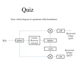
Quiz Draw a block diagram of a quadrature (I/Q) demodulator. LPF Recovered I Data: IR(kT) Carrier Recovery cos(wot) S(t) Splitter Splitter -(p/2) Recovered Q Data: QR(kT) LPF
System Considerations: Receivers/Transmitters • Increased integration of Broadband, High frequency RF components – understanding of the performance and specification limitations of these devices is critical to system designers. • Sensitivity/Minimum Detectable Signal • Transmitter Power • Gain/Bandwidth characteristics • Intermodulation (linearity) • Filter characteristics • Frequency conversion techniques • Active/Passive • Nonlinear/commutating • Balanced/unbalanced • Image/Spurious products • Propagation Issues • Path loss/Fading • Diversity • Frequency Re-use/Co-channel Interference
System Considerations: Receivers/Transmitters (cont) • Modulation/Demodulation Types and techniques • Frequency Translation • Spectrum Shaping • Waveform Synthesis • PLL • Frequency Synthesis • FDMA • TDMA • CDMA • Direct Sequence/Frequency Hopping • Digital Aspects • A/D, D/A, Nyquist • Eb/N0 • BER • Symbol Alphabets • Decision Based modulation/demodulation schemes • Coding/FEC
System Considerations: Receivers Front End Issues T/R antenna switching Diplexers Diversity Switching Preselector/Image rejection Low Noise/ High Gain in first Stage (LNR) Sensitivity power Level S(watts):
Image Reject Mixers vA(t) LPF Local Oscillator cos(wLOt) vo(t) S(t) Splitter Splitter S -(p/2) (p/2) vB(t) LPF High Side Injection: wS = wLO - wIF
vA(t) LPF Local Oscillator cos(wLOt) vo(t) S(t) Splitter Splitter S -(p/2) (p/2) vB(t) LPF
vA(t) LPF Local Oscillator cos(wLOt) vo(t) S(t) Splitter Splitter S -(p/2) (p/2) vB(t) LPF High Side Injection: wIM = wLO + wIF
vA(t) LPF Local Oscillator cos(wLOt) vo(t) S(t) Splitter Splitter S -(p/2) (p/2) vB(t) LPF
Phase Noise Pc f Df f0 frequency
Reciprocal Mixing Example Local oscillator phase noise is characterized with Sc(f)= 60 dBc/hz at 50 kHz displacement from center frequency. The Local Oscillator puts out Pc= +10 dBm, and the IF Bandwidth is 10 kHz. What is the effective LO power available for reciprocal mixing of a strong signal displaced 50 kHz from the desired channel? The phase noise power available to mix with the interfering channel will occupy a bandwidth equal to the IF bandwidth, located 50 kHz away from the LO. Sc(50 kHz) = 60 dBc/hz (1/Sc = 10-6) ; Df= 10 kHz and Pc= 10 mw, therefore the effective LO power for reciprocal mixing with the interfering signal is Pr = (10 mw) (10 kHz)(10-6) = 0.1 mW
Quiz What is the root cause, and what frequency combinations cause third order intermodulation interference? Nonlinear gain causes on-channel interference when strong signals are spaced at Df and 2Df from the desired channel.
Intermodulation Characteristics Po(dBm) 3rd Order Intercept Point PIP,o Response to Signal 1 Response to Interference 3 1 Ps,o SNR 1 Pd,o IMDR PN,o Pi(dBm) PIP,i PSF PN,i Ps,i Pd,i “Spurious Free”
Example An amplifier has a gain of 22 dB and a 3rd order output intercept point of 27 dBm. Assume the effective noise input power is PN,i = -130 dBm. Determine Spurious Free Range PN,i + G = PN,o = Pd,o = 3(PSF + G) – 2PIP,o PSF = (PN,i + 2PIP,o -2G)/3 = (– 130 dBm + 54 dB – 44 dB)/3 = – 40 dBm Determine IMDR for an input signal level of -80 dBm and SNR = 15 dB. Ps,i + G – SNR = Pd,o = 3(Pd,i + G) – 2PIP,o Pd,i = (Ps,i – SNR + 2PIP,o -2G)/3 = (– 80 dBm – 15 dB + 54 dB – 44 dB)/3 = – 28.3 dBm IMDR = – 28.3dBm – (– 80 dBm) = 51.7 dB
PIP,o Ps,o S/N Pd,o PN,o IMDR Ps,i PSF PN,i Pd,i