Download
1 / 30
300 likes | 427 Views
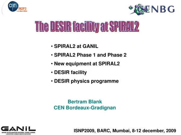
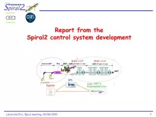
This report provides a comprehensive overview of the Spiral2 project, detailing its current status, planning phases, and control system development. Key elements include the introduction of the Spiral2 facility adjacent to the Ganil facility, first beam tests, system integration, and use of dedicated tools like LabView and the XAL-based framework. The report discusses equipment integration, power supply management, beam diagnostics, and high-level application development, contributing to the successful operation of the Spiral2 accelerator.

E N D
Outline • The Spiral2 project overview and status • Global overview • Planning • First beam tests • Control system introduction • Main options • Use of some specific tools • Equipment integration • Power supplies • Beam diagnostics • LLRF • High level applications • Use of a XAL based framework • Machine description and configuration database • IOC interface • Equipment database management Introduction
The Spiral2 facility beside the Ganil one The Spiral2 project
Planning Existing Ganil facility Phase 1 : Spiral2 Accelerator First beam in 2012 Phase 2 : Spiral2Production First beam in 2013 The Spiral2 project
First beam tests 2010-2011 deuteron beam tests IRFU Saclay 2009-2011 q/a=1/3 beam tests LPSC Grenoble The Spiral2 project
Q/A=1/3 beam tests (LPSC Grenoble) The Spiral2 project
First resultsat LPSC (June 2009) The Spiral2 project
Control systems implementation Existing Ganil : "Ganiciel"Ada based home made control system Spiral2 Accelerator Spiral2 RIB production Ada Control system overview
Main technical choices summary ● Soft IOCs ● Graphical User Interfaces : Epics tools (editor, trends, plots …) Java Programming ● Databases servers PC / Linux RHEL 5.4 3.14.9 Channel Access / Ethernet VME / VxWorks 6.7 IOCs Epics database and sequencer Supervision Siemens S7 PLC Remote I/Os Power supplies I/Os Motorola 5500 CPU VME I/O boards Profibus or Profinet Modbus-RTU / RS485 Modbus-TCP / Ethernet CFs DCCTs ACCTs Alarms Stepping motors RF amplifiers Profilers Control system overview
Use of specific tools • LabView/Epics gateway • Use of the LabView2009 version as a LabView client for Epics servers • To allow existing LabView applications to interface with Epics IOCs (first use : ion source control at LPSC Grenoble) • Ok with some issues reported to National Instruments : • Missing datatypes : boolean, waveform ... • Ability to access to other fields than the .VAL one • CSS (thanks to Kay Kasemir !) • Evaluation of the archiving and restitution plot functionalities • Relying on a MySql database • Will be tested in parallel with the oldest archiver at the deuteron source bench test at CEA-Irfu Saclay • Use of this Eclipse based environment in operation ? • Irmis : cf. equipment data management topic Control system overview
Power supplies • Use of the Modbus/TCP protocol using an interface • Provided by the manufacturer(current power supplies) • Home-made (voltage current supplies) • Software integration High level applications Java integration EDM screen Specific IOC database design Equipment interfaces
Beam diagnostics interface Equipment interfaces
Fast triggered acquisition (CF, DCCT …) • Hardware : Adas VME boards • ICV 108 : Externaltriggering(4 Mo buffer so 2 Msamples) • ICV 178 : 8 x16 bits inputs up to 1,2 Msamples/s • Software • Specific driver • EDMscreen • See F. Gougnaud’spresentation Equipment interfaces
LLRF CC integration • Digital LLRF VME64x FPGA based board (CEA-Irfu) • Handles the pilot voltage to control the phase and amplitude • Controls automatically the startup • Monitors the multipactor phenomena • Provides to the control system the phase difference for the frequency fine tuning • Manages a circular buffer for post-mortem analysis VME64x crates distribution The control system (VME CPU within the VME64x crate, private Ethernet network to communicate with the reactive device,PLC)will have to provide the feedback loop for the frequency tuning : - temperature control of the cooling water for the RFQ, - cavity deformation or plunger and motor for the cavities Equipment interfaces
High level applications framework specification • At the early days … • Java environment decided • Xal (SNS) framework ? • Many capabilities, concepts and powerful • Quite a large number of applications, packages • Ability to be adapted to fit our constraints • Limited manpower • Machine specificities (multiparticles, link with the CEA TraceWin simulation code …) • Integration within our Ganil database design approach • Evaluation (end-2007 mid-2009) • Use of standard Xal applications • Integration of some Spiral2 specificities within Xal existing ones • Evaluation of a Xal-derived application framework for Spiral2 • New applications • Links with the environment (database, simulation code) High level applications
New applications within the Xal derived framework Beam optimization Beam profile viewer High level applications
Development of an alarm manager Display To provide a common alarm manager both for the existing Ganil machine and the future Spiral2 facility Java / log4j based (+log4Ada) • Configuration alarm server database : • PV to be monitored • related display text data (static text, PV to get additional information …) High level applications
Xal style use for Spiral2 • Current status : • Used as a tool box • Spiral2 specificities integrated • Still some questions : • E-logging • Xml and database synchronization • Xal V logger / CSS archiving ? • Plans • First real tests this summer at Saclay : alarms, parameters management, beam profilers display, optimization • Adapt or develop new Xal style applications : alignment, cavity tuning, matching … • Warm thanks to the XAL community and the help we got High level applications
Machine configuration management Sequences Handles Nodes PVs Fitsboth the existing Spiral2 constraints and the Xal concepts Machine configuration database
IOC interface (1/3) • Objective : High level applications would have to interface equipment always in the same way, independently from the IOC implementation and hardware • Codification project rules DDDDD-RRRRRRR[-CCCCCC]:SsssssSsssssEQPT Signal • Need to standardize the interface between the high level applications and the PVs • IOC specific database design • Enhanced codification rules • Settings $(EQPT):ABCDCons • Readbacks $(EQPT):ABCDAct • Measurements $(EQPT):ABCDMes IOC communication
IOC interface (2/3) • genSub record added to provide • Status • Currentstatusword$(EQPT):InterfaceRecord.VALa • Meaning of status bits set to ‘1’ (string array) $(EQPT):InterfaceRecord.VALb • Meaning of status bits set to ‘0’ (string array) $(EQPT):InterfaceRecord.VALc • Defaults • List of current defaults (string array) $(EQPT):InterfaceRecord.VALd • List of all possible defaults (string array) $(EQPT):InterfaceRecord.VALe • Commands • List of availablecommands (string array) $(EQPT):InterfaceRecord.VALf IOC communication
IOC interface (3/3) • Commands • $(EQPT):Cmd mbborecordto sendany command(previously : $(EQPT):OnOff, $EQPT:Resetetc …according to the equipment class) • Currentworkstatus • First implementation for the power supplies interface • Validated for highlevelapplications • To bechecked for the standard Epics toolsintegration (EDM) • To beevaluated for otherequipment types IOC communication
Equipment management Home made database user interface (Java) Template Files Relational database (Ingres) .cmd genIOCJava generation procedures VDCT • Initialization and configuration commands- Substitutions for template files • (Sequences) Irmis (v2) PV crawler Epics IOCs Equipment management
Definition of general configuration Developer use only Exemple : configuration of the Modbus communication (2 command lines to be generated) Command line beginning Command parameters Separators for file generation Equipment management
Définition of equipment type Developer use only Exemple : Definition of the power supply ALIMHZ type Modbus function parameter Substitution macros Separators for file generation
Equipment characteristics End-user Exemple : Configuration of a power supply (instance of an ALIMHZ equipment type) Equipment management
Generated configuration file To be included into the .cmd script From the equipment configuration type From the equipment characteristics Equipment management
Generated substitution file To be included into the .cmd script From the equipment characteristics Equipment management
Work in progress … • Three files to be generated and called from the .cmd file • Configuration file • Substitution file • Sequencer file : not yet implemented ! • Next steps : • Test and validate the model with other equipment types • Faraday Cups measurements • Stepping motors for beam slits • … • Evaluate the integration of PLCs controlled equipment • Think to more complex equipment (emittancemeters …) ? • If necessary, define the links with other databases or tools (Irmis, alarms configuration, CSS archive engines configuration, beam parameters management …) Equipment management
Thanks for your attention … J.F. Denis, F. Gougnaud, J.F. Gournay, Y. Lussignol, P. Mattei J.C. Deroy, P. Duneau, P. Gillette, C. Haquin, E. Lécorché, E. Lemaître, P. Lermine, J.M. Loyant, L. Philippe, J.F. Rozé,D. Touchard P. Graehling, J. Hosselet, C. Maazouzi