Progress Report on CGSE Control System
Progress Report on CGSE Control System. Project Team of SJTU for AMS-02 Yang Yupu AMS TIM @NASA JSC, Jan 8-12, 2007. valves Box. I/O Module. Dewar system. PROFIBUS. PLC. Cryostat. Monitoring PC. CANbus. Magnet. CAB. ( Cryo-magnet Avionics Box). Tasks of CGSE

Progress Report on CGSE Control System
E N D
Presentation Transcript
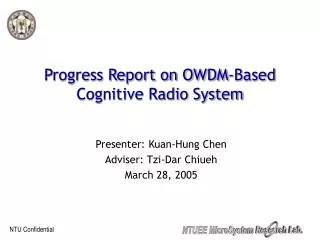
Progress Report onCGSE Control System Project Team of SJTU for AMS-02 Yang Yupu AMS TIM @NASA JSC, Jan 8-12, 2007
valves Box I/O Module Dewar system PROFIBUS PLC Cryostat Monitoring PC CANbus Magnet CAB ( Cryo-magnet Avionics Box) Tasks of CGSE 1 Cooling down the AMS magnet (from 300K to 1.8K) 2 Filling magnet vessel with super-fluidhelium (~2500 lit @1.8 K ) operator station CGSE = Cryogenic Ground Support Equipment
Contents 1 Hardware System Completed 2 Software Modules are Ongoing 2.1 Communicating Module 2.2 Control Algorithm Module 2.3 HMI Module 3 Test Platform for Super-fluid Helium Experiment 4 Further Works
1 Hardware System Completed 1.1 Config of S7-410H controller is finished 1.2 Config of ET200-DP stations is finished 1.3 Hardware of Communication is finished
Hardware System Completed Communication Interface Distributed I/O Module CGSE-Valve Control simulator Magnet Data Simulator Redundant Controller
WinCC HMI Distributed I/O Module Redundant Frofibus Redundant PLC Assembly of the Redundant PLC System in SJTU
Config of S7-414H PLC Structure Config Field-Bus Config PLC 414H Config
2.1 Communicating Module 1 Communicating Module based on CANbus
valves Box I/O Module Dewar system PROFIBUS PLC Cryostat Monitoring PC CANbus Magnet CAB ( Cryo-magnet Avionics Box) Tasks of CGSE 1 Cooling down the AMS magnet (from 300K to 1.8K) 2 Filling magnet vessel with liquid helium (~2500 lit @1.8 K ) operator station CGSE = Cryogenic Ground Support Equipment
CGSE control system need to get from the magnet the following parameters (Confirmed at the TIM@cern April 2006) • Temperatures of helium cooling flow across the magnet T21, T19 and their difference (T21-T19).(from CAB) • (This temperature difference should be not more 50 K during cooling of the magnet in the range 300-80 K ) 2. Helium temperature T07 . (from CAB) ( for control of pumping AMS magnet to super fluid state at 1.8 K ) following parameters for filling up procedure: 3. Signal from helium level meters L02, L03. (CGSE direct from the meters) 4. Pressure in AMS main helium tank P04, P05. (from CAB) 5. Temperatures of the AMS VCS T09-T12 . ( from CAB) 6. AMS temperatures in SFHe Cooling Loop (T01-T06). (from CAB ) 7. Position of AMS valves: open or close. (Some from CAB, some from CGSE and new table from SCL/McMahon 5 May,2006)
1 Communicating Module based on CANbus CAN Master CAN Slave TCP_Client Display Interface Display Interface Display Interface Response and Data Control Command and Receive Data Command and Data Transmitting CAN Slave Port Socket Client port CAN Master Port Socket Server Port CAN Net Ether Net Function ofCAN Master, TCP_Client and CAN Slave 1 CAN Master is mainly used at the connection and communication between CAN networks and TCP/IP networks. It functionally works as angateway. 2 Function of TCP Client is to Simulate CGSE sending commands to TCP Server (CAN Master) through the TCP/IP networks and receiving its response. 3CAN Slave is mainly used to simulatethe slave node (CAB) of CGSE, and implement the functions such as data-feedback, reading the values of locale data-collection equipment, etc.
Display Interface of CAN Master Display Interface of CAN_Slave Display Interface of TCP Client
CAN Slave (CAB of Magnet) TCP_Client CAN Master Ethernet Interface of CGSE-MS FrofiBus Testing of communicationsoftware in SJTU
EPP-CAN Box1 CAN Bus Transmeter Sensor EPP-CAN Box2 EPP-CAN Boxes and temperature sensor in communicationsoftware testing
2.1 Communicating Module 2 Communicating Module for CAB
Magnet CAB Simulator CAB CAB Slave EPP-CAN Box CAN (Linux) EPP-CAN Box FEP CAN Port Ethernet Server socket Magnet Client (Windows) Magnet Client socket Magnet_server / CAB_Master Server socket FEP Client socket Win CC & Other Modules Magnet Data AMS Block CAB Commands OPC General Scheme of Communicating Module for CAB
CGSE-Magnet Date CAB Commands Before After CGSE-Magnet Date CAB Commands Data format used in the module
2.2 Control Algorithm Module 1 Supervising of Status of I/O Stations 2 Testing PID Control Algorithm of Valves 3 Test Module for OPC Link 4 Object Identification Module 5 Control test for large Delay Temperature Process 6 Modified Smith Control Algorithm
3 Test Module for OPC Link OPC is a important protocol used in control industry for easy linking software which produced by different developers. OPC Interaction Module Communication Based on OPC Functions Diagram of OPCInteraction Module
4 Object Identification Module Identification Data Identification Algorithm Identification Result Identification Object y(k)= 0.7093y(k-1) + 0.1260y(k-2)+0.1619y(k-3) +0.0007u(k-15)+ 0.0038u(k-16)
5 Control test for large Delay Temperature Process Control with a high precision for a large delay object is still a challenge in control community. The process of cooling down the Magnet is maybe a large delay control task.
PID Controller Object Output of Predictor Adaptive Smith Predictor Structure Diagram of Modified Smith Control System 6 Modified Smith Control Algorithm (Smith Control Algorithm is a basic method to control delay object, but it is difficult to satisfy for large delay object .)
Standard Smith Controller Predictor Output Our Modified Smith Controller Prediction Ahead Predictive Result of Modified Smith Predictor Response of System with Modified Smith Predictor Simulation Result of Cooling Down for the Magnet
2.3 HMI Module HMI of CGSE Control System Based on Siemens WinCC
4 Control Platform for Super-fluid Helium Experiment In SJTU
Design Requirement • 1 Provide a control and measure system for obtaining, maintaining and transmitting super-fluid helium • Support the function such as multi-data collecting, display, recording and archiving of the process data • Flexible and expandable. Some functional modules in this system are designed to be suitable for other occasions in CGSE
Measurement and Control Platform for super-fluid helium VB6 Environment WIN XP Advantech DLL Driver PCI 1710 AI/AO/DI/DO PCI 1620 B 8-port 232 communicating board COM1 COM2 COM3 COM4 COM5 COM6 AI 0 Temperature instrument #1 Liquid-Level Monitor #1 Flow Meter #1 Temperature instrument #2 Liquid-Level Monitor #2 232 232 232 232 232 Sensor of the pressure difference ADAM4522 232 485 ADAM-4017 ADAM-4024 ADAM-4050 Hardware Schema of the Control Platform The platform is built under MCGS and VB6 environment upon an industrial computer, which communicates with instruments through PCI boards
HMI Controller Signal Connection Box Hardware Assembly of the Control Platform
Software design Platform design Environment Object Strategies design
HMI of Control Platform for Super-fluid Helium Experiment Experiment Platform For Super-fluid Helium Differential Pressure Dewar1 Dewar2 Gas Temperature Liquid Level Flux Gas Temperature Liquid Level Liquid Temperature Pressure Liquid Temperature Pressure
Pipeline of SF Helium Dewar 2 Compressor Dewar 1 Control Platform The Control Platform in the working place of Super-fluid Helium Experiment in SJTU
4 Further Works 1 Continue to perfect the communication the software 2 Continue to configure the Interface between PLC and mechanical system of CGSE. 3 Continue to develop HMI (Human Machine Interface) software based on Siemens WinCC. 4 Continue to develop software modules for whole integration of CGSE in SJTU