Download
1 / 15
150 likes | 281 Views
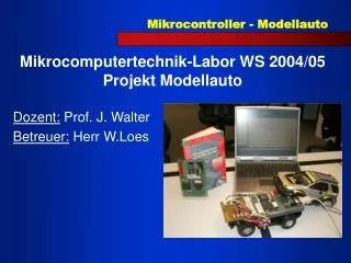
Mikrocomputertechnik-Labor WS 2004/05 Projekt Modellauto. Dozent: Prof. J. Walter Betreuer: Herr W.Loes. Team: Ralf Eschbach Daniel Nold. Inhalt Idee -> Projektbeschreibung Bauteile Zukaufteile Schaltplan Programmablauf / Programmbeschreibung. Idee:

E N D
Mikrocomputertechnik-Labor WS 2004/05Projekt Modellauto Dozent: Prof. J. Walter Betreuer: Herr W.Loes
Team: Ralf Eschbach Daniel Nold
Inhalt • Idee -> Projektbeschreibung • Bauteile Zukaufteile • Schaltplan • Programmablauf / Programmbeschreibung
Idee: Ein Modellauto, soll über Sensoren ein Hindernis erkennen und diesem ausweichen
Realisierung: Mit einem gekauften Modellauto modifiziert mit: Servomotor Senderdiode TSAL 6200 Empfängerdiode Tsop 1733/1740
Leiterplatte Zur Ansteuerung der einzelnen Bauteile
Ansteuerung und Programmablauf Verwendete Chip Komponenten • Timer 0 und 1 Frequenzmodulation • Timer 2 Pulsweitenmodulation
Timer 0 - P3.4 (Senderdiode hinten 33 kHz) Timer 1 - P3.5 (Senderdiode vorne 40 kHz) Timer 2 - P1.1 Compare Register PWM, 3 Stellungen: Periode 20 ms PWM Rechts --> 1 ms PWM Mitte --> 1,2 ms PWM Links --> 1,4 ms Relais 1 -> P3.0 (Spannungsversorgung für Relais 2, 0 = EIN) Relais 2 -> P3.1 (1 = vorwärts, 0 = rückwärts) IR-Empfänger HL -> P1.0 (33 kHz) IR-Empfänger HR -> P1.2 (33 kHz) IR-Empfänger VL -> P1.3 (40 kHz) IR-Empfänger VR -> P1.4 (40 kHz)
Initialisierung Periode_low EQU 0E0H Periode_high EQU 0B1H PWM_rechts_low EQU 0A8H PWM_rechts_high EQU 0FBH PWM_mitte_low EQU 000H PWM_mitte_high EQU 0FBH PWM_links_low EQU 040H PWM_links_high EQU 0FAH Timer0 EQU 0F4H Timer1 EQU 0F3h
Hauptschleife ABFRAGE: mov TCON,#00010000b setb P3.1 clr P3.0 setb P3.2 clr P3.3 call MITTE VOR: jnb P1.0,RECHTS_RUECK jnb P1.2,LINKS_RUECK jmp VOR
Ausweichvorgang RECHTS_RUECK: clr P3.1 clr P3.2 setb P3.3 mov TCON,#01000000b call RECHTS jb P1.3, ABFRAGE jmp ABFRAGE
Lenkeinschlag RECHTS: mov CCL1,#PWM_rechts_low mov CCH1,#PWM_rechts_high mov T2CON,#00010001B call TIMER ret