STS mechanics: Conceptual CAD model development
210 likes | 398 Views
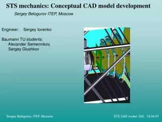
STS mechanics: Conceptual CAD model development. Sergey Belogurov ITEP, Moscow. Engineer: Sergey Iovenko Baumann TU students: Alexander Semennikov, Sergey Glushkov. Outline. Starting point – ALICE SSD mechanics Effect of CBM peculiarities Narrow or wide cabling

STS mechanics: Conceptual CAD model development
E N D
Presentation Transcript
STS mechanics: Conceptual CAD model development Sergey Belogurov ITEP, Moscow Engineer: Sergey Iovenko Baumann TU students: Alexander Semennikov, Sergey Glushkov Sergey Belogurov, ITEP, Moscow STS CAD model. GSI, 19.04.07
Outline • Starting point – ALICE SSD mechanics • Effect of CBM peculiarities • Narrow or wide cabling • Integration of the Stations (sensors, modules, stations) • Particular case – central hole of arbitrary size • Dead gaps in the long sensors • Few words about stereo-strips readout • Mechanical simulations • Conclusions Sergey Belogurov, ITEP, Moscow STS CAD model. GSI, 19.04.07
Starting point – ALICE SSD Ladder, top Principal distinctions: • Barrel geometry ⇒ sag, extra rigidity • Cooling tubes (in our case air cooling is foreseen) • Equal sensors ⇒ translation symmetry ( CBM – variable sensor size due to steep change of the track density vs. angle) • More severe request for minimization of material ALICE SSD girder 0.25 g/cm (≈ Si in CBM) Sergey Belogurov, ITEP, Moscow STS CAD model. GSI, 19.04.07
How our design is affected by the CBM peculiarities \ • The main goal of the conceptual design is to reduce amount of material inside the acceptance and to understand integration of the STS stations. • 1 – We put a rigid frame outside the acceptance and thin support taut for rigidity inside (like a drum or a tennis racket). The support may be either planar or slightly developed in the 3-d dimension. • 2 - Cooling tubes are just removed • 3 - Different length of sensors require variable tilting angle for overlapping • 4 - attempts to minimize material in a single sensor supporting elements should be undertaken 1 Sergey Belogurov, ITEP, Moscow STS CAD model. GSI, 19.04.07
How our design is affected by the CBM peculiarities • The main goal of the conceptual design is to reduce amount of material inside the acceptance and to understand integration of the STS stations. • 1 – We put a rigid frame outside the acceptance and thin support taut for rigidity inside (like a drum or a tennis racket). The support may be either planar or slightly developed in the 3-d dimension. • 2 - Cooling tubes are just removed • 3 - Different length of sensors require variable tilting angle for overlapping • 4 - attempts to minimize material in a single sensor supporting elements should be undertaken 1 The gap, not angle is kept constant 3 Sergey Belogurov, ITEP, Moscow STS CAD model. GSI, 19.04.07
How our design is affected by the CBM peculiarities • The main goal of the conceptual design is to reduce amount of material inside the acceptance and to understand integration of the STS stations. • 1 – We put a rigid frame outside the acceptance and thin support taut for rigidity inside (like a drum or a tennis racket). The support may be either planar or slightly developed in the 3-d dimension. • 2 - Cooling tubes are just removed • 3 - Different length of sensors require variable tilting angle for overlapping • 4 - attempts to minimize material in a single sensor supporting elements should be undertaken 4 1 3 Sergey Belogurov, ITEP, Moscow STS CAD model. GSI, 19.04.07
Narrow or wide cabling? For the discussion of the supporting structure one should decide about width of cables. Narrow cables allow to make more elegant construction. Sergey Belogurov, ITEP, Moscow STS CAD model. GSI, 19.04.07
Integration of the STS stations Basic module for station 6 and station 6 (z=0.5 m) In the case of CBMThere is strong nonuniformity in track density, usage of only one type of the sensors is not possible. Nevertheless we foresee a kind of unification with a concept of basic module for each station. Overlap between modules 4 cm Sergey Belogurov, ITEP, Moscow STS CAD model. GSI, 19.04.07
Integration of the STS stations 7 (z=0.6 m) 8 (z=0.75 m) 9 (z=1.0 m) Sergey Belogurov, ITEP, Moscow STS CAD model. GSI, 19.04.07
Case of the station 8 – arbitrary central hole 90 degree sectors of the station are shifted with respect to each other. It allows to have hole of an arbitrary size Specially designed planar supporting structure may be used for realization of this positioning in a case of narrow cables. Initially special size of central sensors was considered for st. 8. Here we explore another possibility Sergey Belogurov, ITEP, Moscow STS CAD model. GSI, 19.04.07
Case of the station 8 – arbitrary central hole Initially special size of central sensors was considered for st. 8. Here we explore another possibility The modules are mounted alternately from the front and the rear sides and overlapped in the following manner Sergey Belogurov, ITEP, Moscow STS CAD model. GSI, 19.04.07
Case of the station 8 – arbitrary central hole Initially special size of central sensors was considered for st. 8. Here we explore another possibility Note that the leg of a bench-like part is rather short Solution for narrow cables Sergey Belogurov, ITEP, Moscow STS CAD model. GSI, 19.04.07
Case of the station 8 – arbitrary central hole For the wide cabling construction becomes more complicated with 2 separate layers Sergey Belogurov, ITEP, Moscow STS CAD model. GSI, 19.04.07
Dead gaps in the long sensors A problem of the current layout: we overlap the sensors but do not care of the gaps between wafers! Thinking about this problem we had a couple of simple (may be useless) considerations that I would like to communicate now. Sergey Belogurov, ITEP, Moscow STS CAD model. GSI, 19.04.07
Dead gaps in the long sensors A problem of the current layout: we overlap the sensors but do not care of the gaps between wafers! 1. It would be nice if double metal layers allow something like this (contact pads are away from the edge) Sergey Belogurov, ITEP, Moscow STS CAD model. GSI, 19.04.07
Dead gaps in the long sensors A problem of the current layout: we overlap the sensors but do not care of the gaps between wafers! 1. It would be nice if double metal layers allow something like this (contact pads are away from the edge) 2. Some dead gaps are probably unavoidable. In this situation one can try to improve the total efficiency by matching dead regions from different stations with each other. It would be interesting (if feasible) to extend this approach to full CBM. Sergey Belogurov, ITEP, Moscow STS CAD model. GSI, 19.04.07
About readout of stereostrips θ~15°(tgθ=1/4) 3. Double metal connection of the strips inside a sensor may help to control occupancy. Let S1 be an area around a hit, where any other hit would introduce ambiguity in position measurement Let sensor size be 2x4 cm2 N+N channels, S1= S0/8 N+N/2 channels, S1= S0/4 N+N/4 channels, S1= S0/2 N+N/8 channels, S1= S0 Sergey Belogurov, ITEP, Moscow STS CAD model. GSI, 19.04.07
Mechanical simulations Generally mechanical simulations may be used for analysis of the following issues • - Static distribution of stress and deformation under a specified load. • - Eigen frequencies of a mechanical systems • - Dynamic behavior in the vibrating environment. • - Stabilty loss (jumping to another metastable configuration under certain load). • - Thermal effects Currently we are dealing with the first two questions. Carbon fiber composites have a wide range of parameters (factor ~3 for E and s ). Besides, it is an anisotropic material. For plausible simulations we need precise data about material to be used. As a first approximation we took: Tensile modulus (E) 343 GPa Tensile strength (s) 4.7 GPa Poisson ratio 0.25 Density 1.75 g/cm3 Sergey Belogurov, ITEP, Moscow STS CAD model. GSI, 19.04.07
Mechanical simulations (examples) 0.1 Nm ALICE like girder has about 105 SF under weight of the sensors Various loads were applied to the ladder type module, leg cross section 0.3 mm x 1.1 mm Si wafers are well defended from stress in this configuration. One can carefully handle a module without breaking. Sergey Belogurov, ITEP, Moscow STS CAD model. GSI, 19.04.07
Mechanical simulations (examples) Local bending of a combined sensor on the ladder Sergey Belogurov, ITEP, Moscow STS CAD model. GSI, 19.04.07
Conclusions The model reported here is just one of many iterations. It is much easier to make a new model than a real device. However, it seems to be useful to check as early as possible how the detector would look like and what problems would be encountered. We are strongly interested in communications with carbon structures manufacturers and experts, because realistic optimization work should let us to minimize amount of constructive material in CBM Sergey Belogurov, ITEP, Moscow STS CAD model. GSI, 19.04.07