Download
1 / 95
980 likes | 1.35k Views
Conceptual Modeling and Entity-Relationship Diagrams. Chapter 3: Elmasri/Navathe. Outline. Phases of Database Design Conceptual Modeling Abstractions in Conceptual Design Example Database Requirements Deconstructing the E-R Diagram Entities, Attributes and Relationships

E N D
Conceptual Modeling andEntity-Relationship Diagrams Chapter 3: Elmasri/Navathe
Outline • Phases of Database Design • Conceptual Modeling • Abstractions in Conceptual Design • Example Database Requirements • Deconstructing the E-R Diagram • Entities, Attributes and Relationships • Participation, Cardinality and Keys 3753 X2 - 2004
Phases of Database Design Application Domain Requirements Analysis Database Requirements DBMS Independent Conceptual Design Conceptual Schema Data Model Mapping Implementation Schema Physical Design DBMS Dependent Physical Schema 3753 X2 - 2004
A Data Modeling Process • Steps in the data modeling process • Plan project • Determine requirements • Specify entities • Specify relationships • Determine identifiers • Specify attributes • Specify domains • Validate model 3753 X2 - 2004
Planning the Project • Obtaining project authorization and budget • Building the project team • Planning the team’s activities • Establishing tools, techniques, and standards for consistent results • Defining the project’s scope 3753 X2 - 2004
Determining System Requirements • Sources for data modeling requirements • User interviews and user activity observations • Existing forms and reports • New forms and reports • Existing manual files • Existing computer files/databases • Formally defined interfaces (XML) • Domain expertise • The result of the requirements determination will be a repository of notes, diagram, forms reports, files, etc., that can be used to develop the data model 3753 X2 - 2004
Specifying Entities • An entity is something that the users want to track; something the users want to keep data about • Entities • can be physical things or logical concepts • are identifiable; you can tell one from another • are things described by nouns, not characteristics described by adjectives 3753 X2 - 2004
Specifying Relationships • Includes: • Identity of the parent and child entities • Relationship type • Minimum and maximum cardinalities • Name of the relationships • Two techniques: • Examine whether a relationship exists between every combination of two entities • Locate relationships from requirement documents • A combination of the two approaches may be used 3753 X2 - 2004
Determining Identifiers • Identifier is an attribute or group of attributes that uniquely identifies an entity instance • If there is difficulty specifying an identifier, maybe: • it should be part of a different entity • it is a subtype or category of a common entity • it needs one or more identifying relationships 3753 X2 - 2004
Specifying Attributes and Domains • Find attributes on forms, reports, existing files, etc., and add them to entities • Determine whether the attribute has already defined a domain • If so, the attribute is based upon that domain • If not, a new domain is defined • Review the domains and make adjustments as necessary • Domain property inheritance: when the domain properties change, all the attribute properties change as well • Domains may be used to enforce data standards promoting compatible data types and systems • Once all attributes have been specified the model should be reviewed for missing entities 3753 X2 - 2004
Validating Model • Data model is a model of humans’ models, not a model of reality • A data model is wrong if it does not accurately reflect the ways the users think about their world • Data models are validated through a series of reviews • Normally, a team review is followed by user reviews • E-R model as well as prototypes of forms and reports may be used to communicate to users features of the data model 3753 X2 - 2004
Creating Data Models From Forms and Reports • Example: Single entities 3753 X2 - 2004
Example: Identifying Connection Relationships 3753 X2 - 2004
Example: Repeating Groups 3753 X2 - 2004
Example: Repeating Groups 3753 X2 - 2004
Example: Nested Groups 3753 X2 - 2004
Example: Non-Identifying Connection Relationships • Example: 1:1 3753 X2 - 2004
Example: Non-Identifying Connection Relationships 3753 X2 - 2004
Example: 1:N 3753 X2 - 2004
Example: 1:N 3753 X2 - 2004
Example: 1:N 3753 X2 - 2004
Example: N:M 3753 X2 - 2004
Example: Assignment Relationship 3753 X2 - 2004
Example: Assignment Relationship 3753 X2 - 2004
Example: Category Relationship 3753 X2 - 2004
Example: Category Relationship 3753 X2 - 2004
Example: Category Relationship 3753 X2 - 2004
Sales-Order Model 3753 X2 - 2004
Example: Sales Order 3753 X2 - 2004
Example: Sales Order • Figure 3-16(c) shows an alternative design that allows an item to appear more than once on a given order 3753 X2 - 2004
Conceptual Design • Similar to the analysis phase in software development • produce a description of the data • capture the semantics of the data • Description in a high-level model • close to the user’s view of the world • abstract concepts • means of communication between the user and the developer 3753 X2 - 2004
Reasons for Conceptual Modeling • Independent of DBMS. • Allows for easy communication between end-users and developers. • Has a clear method to convert from high-level model to relational model. • Conceptual schema is a permanent description of the database requirements. 3753 X2 - 2004
Abstractions in Conceptual Design • An abstraction is a mental process where we select some set of properties of an object and exclude others. • 3 types of abstractions • classification • aggregation • generalization 3753 X2 - 2004
Classification • Define a class of real-world objects with common properties Month … January February December 3753 X2 - 2004
Aggregation • Define a new class from a set of other classes that represent component parts Car Tires Steering Wheel Engine Gas pedal 3753 X2 - 2004
Generalization • Defines a subset relationship between elements of 2 or more classes Person Employee Student Faculty Staff 3753 X2 - 2004
Entity-Relationship Model • Most popular conceptual model for database design • Basis for many other models • Describes the data in a system and how that data is related • Describes data as entities, attributes and relationships 3753 X2 - 2004
Database requirements • We must convert the written database requirements into an E-R diagram • Need to determine the entities, attributes and relationships. • nouns = entities • adjectives = attributes • verbs = relationships 3753 X2 - 2004
Academic Teaching Database Design an E-R schema for a database to store info about professors, courses and course sections indicating the following: • The name and employee ID number of each professor • The salary and email address(es) for each professor • How long each professor has been at the university • The course sections each professor teaches • The name, number and topic for each course offered • The section and room number for each course section • Each course section must have only one professor • Each course can have multiple sections 3753 X2 - 2004
Visual View of the Database Employee ID Years Teaching Section ID Room Start Date N 1 Section Professor teaches Email N Salary First Part of Name Last 1 Number Course Topic Name
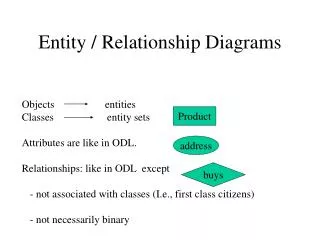
The Pieces • Objects • Entity (including weak entities) • Attribute • Relationship • “Structural” Constraints • Cardinality • Participation 3753 X2 - 2004
Entities • Entity – basic object of the E-R model • Represents a “thing” with an independent existence • Can exist physically or conceptually • a professor, a student, a course • Entity type – used to define a set of entities with the same properties. 3753 X2 - 2004
Number Name Topic Entity Type Course Entity and Entity Types Number: 3753 Name: Database Management Systems Topic: Introduction to DBMSs Entity 3753 X2 - 2004
Attributes • Each entity has a set of associated properties that describes the entity. These properties are known as attributes. • Attributes can be: • Simple or Composite • Single or Multi-valued • Stored or Derived • NULL 3753 X2 - 2004
First Last Professor Composite Name Attributes (cont’d) Simple Professor Start Date 3753 X2 - 2004
Multi-Valued Professor Email Attributes (cont’d) Single Professor Employee ID# 3753 X2 - 2004
Derived Professor Years Teaching Attributes (cont’d) Stored Professor Start Date 3753 X2 - 2004
Attributes (cont’d) • NULL attributes have no value • not 0 (zero) • not a blank string • Attributes can be “nullable” where a null value is allowed, or “not nullable” where they must have a value. 3753 X2 - 2004
Primary Keys • Employee ID is the primary key • Primary keys must be unique for the entity in question Professor Employee ID 3753 X2 - 2004
Relationships • defines a set of associations between various entities • can have attributes to define them • are limited by: • Participation • Cardinality Ratio 3753 X2 - 2004