Download
1 / 28
280 likes | 414 Views
This presentation by Hanna Alam and Yousef Badran, supervised by Yossi Hipsh, covers the design and testing of a microstrip line for a high-speed communication channel operating at 100GB/s. The agenda includes an introduction to fast-evolving digital systems, project goals, transmitter and receiver schematics, microstrip line design, loss considerations, and testing methods. The focus is on developing a robust microstrip line suitable for high-frequency applications and exploring suitable components for improving signal integrity.

E N D
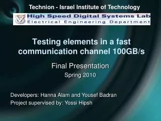
Technion- Israel Institute of Technology Testing elements in a fast communication channel 100GB/s Final Presentation Spring 2010 Developers: Hanna Alam and YousefBadran Project supervised by: YossiHipsh
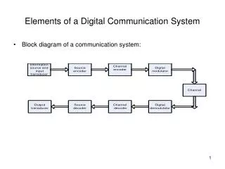
Agenda • Brief Introduction • Project Goals • Transmitter and Receiver Schematic • Designing the Microstrip Line • Losses Considerations • Testing the Microstrip Line • Components and Suitable Devices • Conclusions and next steps
Introduction • The Fast evolving high-speed digital systems in today’s technology and in daily life • Using tools and technologies which we currently possess in order to create a more advanced design • A method for breaching the 100 GB/s barrier is through channels with lower frequencies
Goals • The ability to transfer information in a single100GB/s rate channel between two units located on the same printed board • Designing and characterizing the microstrip line • Suggest theoretical and practical way to test the microstrip line in terms of signal integrity and internal losses
Unit1– Transmitter’s side 25GB/s 100GB/s
Unit1– Transmitter’s side • Sharpening the signal to reduce rise and fall • time: • Problem : finding a suitable buffer • In lower frequencies we use step recovery • diodes, in higher frequencies the issue • requires further researching
Unit1– Transmitter’s side • Reducing the bit time is achieved by a mixer and a power divider • Delay is required in order to achieve the desired result • Also requires additional researching
Unit2– Receiver’s side 25GB/s 100GB/s
Unit2– Receiver’s side • The attenuation of the microstrip line is not uniform. The higher the frequencies the greater are the losses • Equalizer - to compensate on the different losses preserving SI • Monostable - to increase the bit time back to the original 40ps state
The µstrip Line • primary objective is designing a microstrip line on a printed circuit board • Our focus will be on a 15 cm long microstrip line. • How to begin our design ?
Designing the µstrip • First step is finding a suitable dielectric material for high frequency as 100 GHz • Next, calculating and choosing microstrip line parameters considering technological constrains • Additional possible modification that can be added
Duroid 5580 • Duroid 5580 manufactured by Rogers Corporation
Modeling the µstrip line The demand for Uniform EM field in the H«λ µstrip line “H” is the dielectric height, What is λ? We chose H=0.127mm = 5 mil
Modeling the µstrip line • What about conductor’s width, W? • W is determined by the requirement for a standard resistance of 50Ω • As shown in the booklet we acquire that: W=15.5 mil
Basic µstrip line • Summing up basic µstrip line parameters:
Line modification • Shielded microstrip line: • Reduces cross-talk • Significantly improves energy advancement through the µstrip line
Line modification • Suspended microstrip • Foam-like material dielectric layer • dielectric constant close to unity • Much lower losses approximately 1:5 ratio - complicates manufacturing process
Losses Considerations • Accurate losses equations are complicated, they’re explained in chapter 3 in the booklet • Approximation: • Typical Duroid loss = 0.3 dB/λ • Microstrip length = 15 cm • λ(min) = 0.2 cm • Expected total losses = 22.5 dB • This graph can be verified by SI simulations Internal Loss f[GHz]
Testing the µstrip line • We need to measure the losses in the microstrip line in order to configure the equalizer or the pre-emphasis unit • 100GHz pulses are hard to create, therefore we can calculate the Fourier series and deal with several lower frequencies individually • This can be easily created using a simple signal generator
Testing the µstrip line • A pulse signal can be split to a sum of sinusoidal signals in different frequencies by calculating its Fourier series example:
Testing the µstrip line • Multiplying the signal to reach 100GHz frequency • Running it through the microstrip line • Using a mixer we decrease the frequency to a measuring level • We repeat the process for additional various frequencies • Enough points can give the losses vs. frequencies graph
Testing the µstrip line First schematic for 100GHz components :
Testing the µstrip line Second schematic for 50GHz components :
Testing the µstrip line Third schematic for 25GHz components :
Suitable Components • EVA-ADF4350 is the supposed unit to generate a stable 0.5:4.4 GHz signal for the testing environment • We deal with this unit as a black box with given parameters • Other components can be found in our booklet appendix B
Conclusions & Next Steps • Researching devices to sharpening the signal in unit-1, and additional units presented in the booklet • Simulating the microstrip line using 3D simulation software such as “CST” • Fabricating the design and testing it • We’ve found various suitable devices that can operate in 100GHz frequency and more • We have presented a HF medium in addition to testing environment
thank you … Questions?