Understanding Processor Timing: Microprocessor Operation and Instruction Execution Cycle
This chapter delves into the fundamental workings of a microprocessor, specifically focusing on the instruction execution cycle comprising fetch, decode, execute, and repeat phases. Using a practical example with initial register values and an assembly instruction, it illustrates how the program counter (IP) is incremented and the instruction is processed step-by-step. Additionally, it covers detailed timing diagrams for memory read and write operations for the 8088 microprocessor, providing insights into the intricacies of CPU operations and memory interactions.

Understanding Processor Timing: Microprocessor Operation and Instruction Execution Cycle
E N D
Presentation Transcript
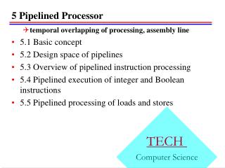
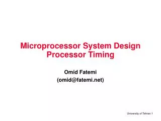
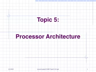
Chapter 5 Processor Timing
How does the Microprocessor works? • Fetch • Increment Program Counter by 1 (IP=IP+1) • Decode • Execute • Repeat
Example ;assume that initially ;ds = 2000, bx = 0023, ax = 351C ;cs = 1000, ip = 0005 mov [bx], al ;8807 hlt ;F4
CPU MEMORY FETCH CS:IP
FETCH 1000:0005
FETCH 10005
FETCH 10005 LOW HIGH
FETCH 10005 88 LOW HIGH
FETCH 10005 88 LOW HIGH
DECODE mov [bx], ?
FETCH CS:IP
FETCH 1000:0006
FETCH 10006
FETCH 10006 LOW HIGH
FETCH 10006 07 LOW HIGH
FETCH 10006 07 LOW HIGH
DECODE mov [bx], al
EXECUTE mov [bx], al DS:BX
EXECUTE mov [bx], al 2000:0023
EXECUTE mov [bx], al 20023
EXECUTE mov [bx], al 20023 1C
EXECUTE mov [bx], al 20023 1C HIGH LOW
EXECUTE mov [bx], al 20023 1C HIGH LOW
FETCH CS:IP
FETCH 1000:0007
FETCH 10007
FETCH 10007 LOW HIGH
FETCH 10007 F4 LOW HIGH
FETCH 10007 F4 LOW HIGH
INC. PC 10007 F4 LOW HIGH
INC. PC 10007 F4 LOW HIGH
DECODE 10007 F4 LOW hlt HIGH
EXECUTE hlt
Machine Cycle Timing Diagram Instruction Cycle
Processor Timing Diagram of 8088 for Memory Read T1 T2 T3 T4 CLOCK __ DT/R ALE AD7 - AD0 A7 - A0 D7 - D0 (from memory) A15 - A8 A15 - A8 A19/S6 - A16/S3 A19 - A16 S6 - S3 __ IO/M ____ RD ______ DEN
Processor Timing Diagram of 8088 for Memory Write T1 T2 T3 T4 CLOCK __ DT/R ALE AD7 - AD0 A7 - A0 D7 - D0 (from CPU) A15 - A8 A15 - A8 A19/S6 - A16/S3 A19 - A16 S6 - S3 __ IO/M ____ WR ______ DEN