Download
1 / 44
440 likes | 847 Views
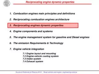
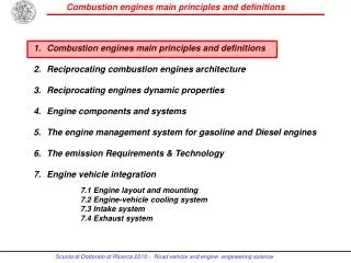
Combustion engines main principles and definitions Reciprocating combustion engines architecture Reciprocating engines dynamic properties Engine components and systems The engine management system for gasoline and Diesel engines The emission Requirements & Technology

E N D
Combustionenginesmainprinciples and definitions Reciprocating combustionengines architecture Reciprocating engines dynamic properties Engine components and systems The engine management system for gasoline and Diesel engines The emission Requirements & Technology Engine vehicle integration 7.1 Engine layout and mounting 7.2 Engine-vehicle cooling system 7.3 Intake system 7.4 Exhaust system
Combustionenginesmainprinciples and definitions Definitions and Classification criteria Reciprocatic EngineBasicGeometry and Terminology Four-strokecycles / Diesel vs Otto cycle Two-strokecycle Engine power and efficiency • John Heywood, Internal Combustion Engine Fundamentals / McGraw-Hill • Charles F. Taylor, The internal Combustion Engine in Theory and Practice /The M.I.T. Press • Automotive Handbook – R. Bosch/SAE • Advanced engine technology (Heinz Heisler) – Butterworth/Heinemann
Combustion Engine Definiton Combustion engines are machines that deliver mechanical work through a linked thermal and combustion process: mechanical work is obtained from the chemical bound energy of the fuel (fuel energy) through combustion by means of thermal energy. In the reciprocating engines the working chamber has rigid walls: the stroke of one of the these walls (pistons) provides a variable volume. The work output is gained from the gas pressure
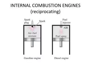
Main Classification Criteria • Gas Exchange • 4 stroke-cycle: working chamber volume is used alternately for work output and gas exchange • 2 stroke-cycle: gas exchange occurs between the working cycles by scavenging the exhaust gasses with a fresh cylinder charge • Charge pressure – Naturally aspirated or supercharged engine • Fuel delivery – Carburetor, undirected or direct injection • Fuel type – Gasoline, Diesel fuel, gas, alcohol…. • Ignition type – Spark or compressed ignited engines (external or self-ignition engines) • Load control – Control by managing the variation of introduced air (gasoline) or introduced fuel (diesel engines)
Reciprocatic Engine Basic Geometry and Terminology • Top Dead Center(TDC):the position of a piston in which it is farthest from the crankshaft, or nearest to the cylinder head. • Bottom Dead Center (BDC): the position of a piston in which it is nearest to the crankshaft, or farthest from the cylinder head. • Cylinder Bore (D): the diameter measurement of the cylinders in a piston engine. Assuming the clearance almost zero, it is may be considered also the outer diameter of the piston. • Stroke (s): the lengthof the pistonmotionbetween TDC and BDC, • covered from the piston in both directions. The distance doubles the Crank • radius r (distance between crank pin and crank center)
Reciprocatic Engine Basic Geometry and Terminology • Piston crown surface area (Ap): equals the piston surface area in case of flat-topped pistons • Displaced cylinder volume (Vd): volume displaced form the piston • during one stroke • Engine displacement (V): single cylinder displacement multiplied by the cylinders number (z)
Reciprocatic Engine Basic Geometry and Terminology • Compression ratio ( ): the ratio between the volume of the cylinder, when the piston is at the bottom of its stroke (BDC), and the volume when the piston is at the top of its stroke (TDC). This volume is called “clearance volume” (Vc): • Typical values of the compression ratio are: • 9 – 12 for spark ignition engines • 16 – 20 for compression ignition engines
Reciprocatic Engine Basic Geometry and Terminology • Ratio of crank radius to connecting rod length • The ratio affects the piston motion equation and therefore the forces applied by the piston to the walls and to the connecting rod: particularly multiplies the second order inertial forces. • Typical values are: • 0.25 - 0.35 for small/medium size engines • 0.10 – 0.20 for large marine engines
Reciprocatic Engine Basic Geometry and Terminology • Bore/stroke ratio • An engine, that has equal bore and stroke, has a bore/stroke value of 1 and is called a square engine. Usually engines that have a bore/stroke ratio of 0.95 to 1.04 are referred as square engines (generally passenger car engines). • An engine, that has wider bore vs. stroke, has a bore/stroke value of over 1 and is referred as “over square” or “short stroke” engine (sport/racing and motorcycle engines). This configuration is generally considered to be a positive trait, since a longer stroke means greater friction and a weaker crankshaft. An “over square” engine is generally more reliable, wears less, and can be run at a higher speed; though with the aid of modern technology, the disadvantages “under square” or “long stroke” engines have been overcome. • An engine, that has shorter bore vs. stroke, has a bore/stroke value of under 1 and is called an “under square” or “long stroke engine” (marine engines). This can be a negative trait for the reasons listed above and because a smaller bore means smaller valves which restricts gaseous exchange; low end torque and fuel economy can be better for a more compact design of the combustion chamber and therefore higher knocking resistance (higher compression ratio). “Under square” engines are typically shorter in length, but heavier and taller than equivalent “over square” ones, which is one of the reasons why this type of engine is not generally used.
Reciprocatic Engine Basic Geometry and Terminology Crankshaft angular velocity: Angular velocity (rad/s) vs engine speed (rpm) Number of crank revolutions for each power stroke Number of engine revolutions necessary to complete one power cycle: two revolutions for four stroke engine and one for two stroke engine. The combustion cycles per unit time is therefore a factor K for engine speed (K = 1 for two stroke-engine and K = 2 for four-stroke engine):
Reciprocatic Engine Basic Geometry and Terminology Mean piston velocity vm: the mean speed of the piston during a complete crankshaft revolution covering two strokes (s): • Typical values of mean piston speed velocity are: • 27 m/s for Race engines • 10-24 m/s for Passenger car gasoline engines (NA) • 12-16 m/s for Passenger car Diesel engines • 8-14 m/s for Truck Diesel engines (turbocharged) • The maximum piston velocity is 60-65%v higher than the mean velocity and is dependent on the connecting-rod to crank radius ratio.
Nikolaus Otto was born in Holzhausen, Germany on 10th June 1832. In his early years he began experimenting with gas engines and completed his first atmospheric engine in 1867. In 1872 he joined with Gottlieb Daimler and Wilhelm Maybach and in 1876 developed the first 4-stroke cycle internal combustion engine based on principles patented in 1862 by Alphonse Beau de Rochas. Although Otto's patent claim for the 'Otto Cycle' was invalidated in 1886, his engineering work led to the first practical use of the 4-stroke cycle which was to provide the driving force for transportation for over a century. Nikolaus Otto died on 26th January 1891. Four-stroke Otto cycle
Four-stroke Otto cycle (Port injection/Indirect injection) Induction Stroke The induction stroke is generally considered to be the first stroke of the Otto 4-Stroke Cycle. At this point in the cycle, the inlet valve is open and the exhaust valve is closed. As the piston travels down the cylinder, a new charge of fuel/air mixture is drawn through the inlet port into the cylinder. The adjacent figure shows the engine crankshaft rotating in a clockwise direction. Fuel is injected through a sequentially controlled port injector just behind the inlet valve. Spark Ignition Spark ignition is the point at which the spark is generated at the sparking plug and is an essential difference between the Otto and Diesel cycles. It may also be considered as the beginning of the power stroke. It is shown here to illustrate that due to flame propagation delays, spark ignition timing commonly takes place 10 degress before TDC during idle and will advance to some 30 or so degrees under normal running conditions. Compression Stroke The compression stroke begins as the inlet valve closes and the piston is driven upwards in the cylinder bore by the momentum of the crankshaft and flywheel.
Four-stroke Otto cycle (Port injection/Indirect injection) Exhaust and Inlet Valve Overlap Exhaust and inlet valve overlap is the transition between the exhaust and inlet strokes and is a practical necessity for the efficient running of any internal combustion engine. Given the constraints imposed by the operation of mechanical valves and the inertia of the air in the inlet manifold, it is necessary to begin opening the inlet valve before the piston reaches Top Dead Centre (TDC) on the exhaust stroke. Likewise, in order to effectively remove all of the combustion gases, the exhaust valve remains open until after TDC. Thus, there is a point in each full cycle when both exhaust and inlet valves are open. The number of degrees over which this occurs and the proportional split across TDC is very much dependent on the engine design and the speed at which it operates. Power Stroke The power stroke begins as the fuel/air mixture is ignited by the spark. The rapidly burning mixture attempting to expand within the cylinder walls, generates a high pressure which forces the piston down the cylinder bore. The linear motion of the piston is converted into rotary motion through the crankshaft. The rotational energy is imparted as momentum to the flywheel which not only provides power for the end use, but also overcomes the work of compression and mechanical losses incurred in the cycle (valve opening and closing, alternator, fuel pump, water pump, etc.). Exhaust Stroke The exhaust stroke is as critical to the smooth and efficient operation of the engine as that of induction. As the name suggests, it's the stroke during which the gases formed during combustion are ejected from the cylinder. This needs to be as complete a process as possible, as any remaining gases displace an equivalent volume of the new charge of fuel/air mixture and leads to a reduction in the maximum possible power.
Four-stroke Otto cycle (Direct Injection) Otto Cycle Operation with Direct Injection The theoretical Otto Cycle process is the same for both indirect and direct fuel injection methods, but the efficiencies gained by using direct injection are bringing the practical application closer to the theoretical. Direct injection means that there is a total separation between the air and fuel required for combustion. This allows precise control over the quantity of fuel and the time in the cycle it is introduced into the cylinder. Thus, for maximum power (in similar manner to that of a port injection system), it is possible to inject a full quantity of fuel in the induction stroke, while for low load, maximum economy (lean-burn) operation it is possible to inject a smaller quantity of fuel during the compression stroke. Although lean-burn is implemented with indirect injection, the lean-burn misfire limit (point at which misfire occurs) is governed by the leanness of the fuel/air mixture in the cylinder. This limit is lowered in direct injection, spark ignition engines, as the fuel spray is directed towards the sparking plug to ensure that there is a chemically adequate mixture around the plug when the spark occurs.
Four-stroke Diesel cycle Rudolph Diesel was born in Paris of Bavarian parents in 1858. As a budding mechanical engineer at the Technical University in Munich, he became fascinated by the 2nd law of thermodynamics and the maximum efficiency of a Carnot process and attempted to improve the existing thermal engines of the day on the basis of purely theoretical considerations. His first prototype engine was built in 1893, a year after he applied for his initial patent, but it wasn't until the third prototype was built in 1897 that theory was put into practice with the first 'Diesel' engine.
Four-stroke Diesel cycle Compression Ignition Compression ignition takes place when the fuel from the high pressure fuel injector spontaneously ignites in the cylinder. In the theoretical cycle, fuel is injected at TDC, but as there is a finite time for the fuel to ignite (ignition lag) in practical engines, fuel is injected into the cylinder before the piston reaches TDC to ensure that maximum power can be achieved. This is synonymous with automatic spark ignition advance used in Otto cycle engines. Induction Stroke The induction stroke in a Diesel engine is used to draw in a new volume of charge air into the cylinder. As the power generated in an engine is dependent on the quantity of fuel burnt during combustion and that in turn is determined by the volume of air (oxygen) present, most diesel engines use turbochargers to force air into the cylinder during the induction stroke. Compression Stroke The compression stroke begins as the inlet valve closes and the piston is driven upwards in the cylinder bore by the momentum of the crankshaft and flywheel. The purpose of the compression stroke in a Diesel engine is to raise the temperature of the charge air to the point where fuel injected into the cylinder spontaneously ignites. In this cycle, the separation of fuel from the charge air eliminates problems with auto-ignition and therefore allows Diesel engines to operate at much higher compression ratios than those currently in production with the Otto Cycle.
Four-stroke Diesel cycle Power Stroke The power stroke begins as the injected fuel spontaneously ignites with the air in the cylinder. As the rapidly burning mixture attempts to expand within the cylinder walls, it generates a high pressure which forces the piston down the cylinder bore. The linear motion of the piston is converted into rotary motion through the crankshaft. The rotational energy is imparted as momentum to the flywheel which not only provides power for the end use, but also overcomes the work of compression and mechanical losses incurred in the cycle (valve opening and closing, alternator, fuel injector pump, water pump, etc.). Exhaust and Inlet Valve Overlap Exhaust and inlet valve overlap is the transition between the exhaust and inlet strokes and is a practical necessity for the efficient running of any internal combustion engine. Given the constraints imposed by the operation of mechanical valves and the inertia of the air in the inlet manifold, it is necessary to begin opening the inlet valve before the piston reaches Top Dead Centre (TDC) on the exhaust stroke. Likewise, in order to effectively remove all of the combustion gases, the exhaust valve remains open until after TDC. Thus, there is a point in each full cycle when both exhaust and inlet valves are open. The number of degrees over which this occurs and the proportional split across TDC is very much dependent on the engine design and the speed at which it operates. Exhaust Stroke The exhaust stroke is as critical to the smooth and efficient operation of the engine as that of induction. As the name suggests, it's the stroke during which the gases formed during combustion are ejected from the cylinder. This needs to be as complete a process as possible, as any remaining gases displace an equivalent volume of the new charge air and leads to a reduction in the maximum possible power.
Thermal efficiency of the constant-volume cycle (Otto) and pressure-constant cycle (diesel) vs compression ratio
Diesel vs Otto engine Advantages • Higher thermal efficiency as a consequence of a higher compression ratio (16-20 vs 9-12) needed for the self ignition of the mixture • Higher efficiency at part load condition (city driving) because of the different load control with much inferior pumping loss for aspirating air into the cylinder: load control directly by varying the fuel delivery, while in the Otto engine by varying the air through an intake throttle • Less energy spent to produce Diesel fuel Disadvantages • Higher weight for same power delivery, because of higher thermal and mechanical stresses due to higher temperatures and pressures , almost double vs Otto engine, at the end of compression and combustion phases • Lower maximum engine speed because a slower combustion process and higher weight of the rotating an oscillating masses • Engine roughness that generates higher structural and airborne vibration/noise.
Two-stroke cycle • Two-stroke cycle • Gas exchange occurs between the working cycles by scavenging the exhaust gases with a fresh cylinder charge • Control mostly via intake end exhaust ports • In contrast to the four-stroke cycle , no valve train is necessary, but a blower is need for scavenging air
Four stroke vs Two-stroke cycle Advantages • 4-stroke engine • High volumetric efficiency over a wide engine speed range • Low sensitivity to pressure losses in the exhaust system • Effective control of the charging efficiency trough appropriate valve timing and intake system design • 2-stroke engine • Very simple and cheap engine design • Low weight • Low manufacturing cost • Better torsional forces pattern Disadvantages • 4-stroke engine • High complexity of the valve control • Reduced power density because the work is generated only every second shaft rotation • 2-stroke engine • Higher fuel consumption • Higher HC emissions because of a problematic cylinder scavenging • Lower mean effective pressure because of poorer volumetric efficiency • Higher thermal load because no gas echange stroke • Poor idle because of high residual gas percentage into the cylinder
Engine power and efficiency The indicated work Wi [J] is the work of the gas force on the piston per combustion cycle: whereis the gas pressure and the displacement Where indicated cycle means the real cycle (pressure vs displacement) that includes all internal losses occurring in both high pressure and low-pressure processes as due by real working gas, residual exhaust gas, wall heat losses, gas losses, charge cycle negative work.
Engine power and efficiency The indicated powerPi [W]is the derivative of the indicated work vs time. At engine stationary conditions, assuming also constant the work Wi through the cycles, the indicated power is the product of the indicated work and the engine speed n[s-1] divided by the number K of crank shaft revolutions necessary to complete one work cycle. where K=2 for 4-stroke and K=1 for 2-stroke engines The mean indicated pressure represents the indicated work per combustion cycle normalized by the displacement volume: The customary units are J/m3 = Nm/m3 = N/m2 = Pa (bar)
Engine power and efficiency The indicated power is linked to the mean indicated pressure by The indicated efficiency hiis the ratio between the indicated power and the fuel thermal potential [W], which is the product of the fuel mass per time unit and the fuel heating value Hci[J/kg]:
Heat of combustion • The heating value or calorific value of a substance, usually a fuel or food, is the amount of heat released during the combustion of a specified amount of it. The calorific value is a characteristic for each substance. It is measured in units of energy per unit of the substance, usually mass, such as: kcal/kg, kJ/kg, J/mol, Btu/m³. Heating value is commonly determined by use of a bomb calorimeter. • The heat of combustion for fuels is expressed as the HHV, LHV, or GHV: • The quantity known as higher heating value (HHV) (or gross calorific value or gross energy or upper heating value) is determined by bringing all the products of combustion back to the original pre-combustion temperature, and in particular condensing any vapor produced. This is the same as the thermodynamic heat of combustion since the enthalpy change for the reaction assumes a common temperature of the compounds before and after combustion, in which case the water produced by combustion is liquid. • The quantity known as lower heating value (LHV) (or net calorific value) is determined by subtracting the heat of vaporization of the water vapor from the higher heating value. This treats any H2O formed as a vapor. The energy required to vaporize the water therefore is not realized as heat.
Heat of combustion Heat of Combustion for some common fuels (higher value)
Engine power and efficiency The brake powerPmis the product of the angular velocity w[rad/s] and the brake torque C: The effective power output Pm at the output shaft is lower than the indicated power at piston level because of the frictional power Pf includes the frictional losses inside the engine, as piston, piston rings and bearings, and also the power requirements for necessary auxiliary, as oil and water pumps, valve train drive, accessory drive (power steering, alternator drive, air conditioning compressor) The frictional power Pf
Engine power and efficiency The brake mean effective pressure pme, defined by an analogy to the indicated mean pressure, represents the output work per combustion cycle normalized by the displacement volume (also called output specific work): The mechanical efficiency is: and also: Where pmf represents the frictional mean pressure per combustion cycle normalized by the displacement volume.
Engine power and efficiency The brake specific fuel consumption Cs is the ratio between the fuel mass per time unit [g/h] and the engine output power Pm [kW] e the used unit is [g/kWh]: The engine efficiency is the inverse of the specific fuel consumption.
Engine power and efficiency The A/F ratioof the burningmixtureis the ratio between the air mass [kg/s] and the fuel mass [kg/s] per time unit : Ideal theoretical complete combustion is available at a mass ratio of 14.7:1 which is termed as the stoichiometric ratio, i.e. 14.7 kg of air are required to burn 1 kg of fuel. The excess-air factor or air characteristic (lambda) has been chosen to indicate how far the actual A/F mixture deviates from the theoretically ideal mass ratio: defines the ratio of the actually supplied air mass to the theoretically air mass required for complete combustion.
Engine power and efficiency =1, the inducted air mass correspondsto the theoretically required air mass, <1, this indicates air deficiency and therefore a rich A/F mixture: maximum power output results at = 0.85-0.95 >1, in this range there is an air surplus or lean mixture. The excess-air factor is characterized by reduced fuel consumption, but also by reduced power output. With exception of the full load area, the spark ignition engines operate at lambda one (feedback system by lambda sensor) in a wide range of part load at working temperature to guarantee the highest conversion of the 3-way catalyst and to optimize the fuel consumption. In the compression ignited engines (diesel), because the load control is managed through the fuel supply, the lambda factor ranges from about 5 at idling to about 1 at full power: lambda factor of 5 corresponds to about 70 A/F ratio
Engine power and efficiency Pollutants Performances NOx POWER HC BSFC BSFC CO l l Exhaust emissions, performance and brake specific fuel consumption vs lambda factor (spark ignition engines)
Diesel The Combustion Process In the internal combustion engines the combustion is the fundamental process which converts the chemical energy of the fuel in thermal energy inside the combustion chamber. This thermal energy is then converted into mechanical energy through the piston-con rod- crankshaft system. The combustion is a chemical reaction between the air and the fuel generally composed by a mixture of different hydrocarbons molecules. The reaction can be simplified as follows: The ideal combustion process should produce only carbon dioxide (CO2) and water vapor (H2O). Instead the real combustion process produces also some exhaust gases which are the products of an uncompleted oxidation as carbon monoxide (CO), unburnt hydrocarbons (HC), nitrogen oxides (NOx) and per particulate matter (PM). gasoline m (g/km) Cl (l/100 km)
14 30% (l/100 Km) 12 10 20% CO2 (g/Km) 8 6 30-50% ($/100 Km) 4 2 1000 1200 1400 1600 1800 2000 2200 CONSUMO* VEICOLI PASSEGGERI MOTORI BENZINA VS DIESEL AD INIEZIONE DIRETTA Motori benzina 30% Consumo Combustibile (l/100 km) Motori DDI Peso Veicolo (kg) (*) MISURATO su NEDC Pag. 5.5
Engine power and efficiency The volumetric efficiency hv is a measure for the fresh charge introduced in the engine cylinder and is defined by the ratio of the fresh charge ma per cycle and the theoretical charge per combustion cycle filling the geometric displacement V with air at ambient conditions , being therefore the theoretical charge density: Practically the volumetric efficiency represents the capacity of exploiting the cylinder displacement. By supercharging, i.e. by compressing the air before it enters the cylinder, the density is risen and then the engine power that is proportional to the air mass flow.
Engine power and efficiency The output powerPmmaybe also defined as depending on the fuel mass rate trhough the engine efficiency and the fuel heating value Considering the A/F ratio of the mixture and of volumetric efficiency, the output poker also depends on the air mass rate because it equals
pme of typical 4 cylinder engines 15 14 Engine BMEP [bar] 13 12 11 10 9 8 7 1500 2000 2500 3000 3500 4000 4500 5000 5500 6000 6500 7000 7500 8000 8500 Engine Speed [RPM]
pme of typical 6 cylinder engines 15 14 Engine BMEP [bar] 13 12 11 10 9 8 7 1500 2000 2500 3000 3500 4000 4500 5000 5500 6000 6500 7000 7500 Engine Speed [RPM]
pme of 6 cilinder turborchaged and naturally aspirated engines 20 19 18 Engine BMEP [bar] 17 16 15 14 13 12 11 10 9 8 1500 2000 2500 3000 3500 4000 4500 5000 5500 6000 6500 7000 7500 Engine Speed [RPM]
pme of turbodiesel engines 24 22 Engine BMEP [bar] 20 18 16 14 12 10 8 6 4 1000 1500 2000 2500 3000 3500 4000 4500 5000 Engine Speed [RPM]