Download
1 / 22
240 likes | 271 Views
Investigating the onset of successful combustion in homogeneous charge and the impact of complex fluid dynamics on flame development in spark-ignited engines. Analyzing parameters affecting flame behavior, burning angles, and flamelet equations.

E N D
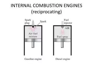
Combustion in SI Engines P M V Subbarao Professor Mechanical Engineering Department A n Effect due to Complex Fluid Dynamic & Thermo-chemical ActivitiesS…
Onset of A Successful Combustion in Homogeneous Charge • A successful spark creates a shock wave in the air-fuel mixture. • This shock wave expands against air fuel mixture. • A photographic study of the phenomena controlling the initial behaviour of spark-ignited flames confirmed that combustion starts as self-ignition. • This self ignition occurs in the volume of very hot gases (kernel) behind the shock wave. • Spark-ignited flames pass through a non-steady propagation period before reaching a steady speed. • This transient period is relatively important, compared to the total time available for combustion, in an engine cycle.
Phases in Flame Development Flame development angleDqd – crank angle interval during which flame kernal develops after spark ignition. Rapid burning angleDqb – crank angle required to burn most of mixture Overall burning angle - sum of flame development and rapid burning angles Mass % of burned Fuel CA
Mixture Burn Time B Scomb : Flame velocity If we wish 90% of fuel to burn during of 50o crank angle. N (rpm) t90%(ms) Scomb,req (m/s) Standard car at idle 500 16.7 3.0 Standard car at max power 4,000 2.1 23.8 Formula car at max power 19,000 0.4 125
Equation for Laminar burning velocity, Su ri : Initial radius of flame or radius of shock wave. rb : instantaneous radius of growing flame. Few more parameters, which cannot be directly parameterized.
Empirical Correlations to Select Combustion Parameters T in K & p in atm.
Mixture Burn Time B If we take a typical value of 50o crank angle for the overall burn N (rpm) t90%(ms) Scomb,req (m/s) Standard car at idle 500 16.7 3.0 Standard car at max power 4,000 2.1 23.8 Formula car at max power 19,000 0.4 125 How is Otto’s Engine Ran at higher Speed????
Mercedes 35 PS : 1901 Sein vorne angeordneter Vierzylinder-Reihenmotor ist direkt mit dem erstmals aus Stahlblech gepressten Rahmen verschraubt und leistet sensationelle 35 PS. Die Drehzahlregelung zwischen 300/min und 1000/min erfolgt über einen Hebel am Lenkrad. Zylinder und Zylinderkopf bilden eine Einheit, das Kurbelgehäuse besteht erstmals aus Aluminium. Its four-cylinder row engine arranged in front is bolted direct with the framework pressed for the first time from steel sheet and carries sensational 35 HP out. Speed regulation between 300/min and 1000/min is made by a lever at the steering wheel. Cylinders and cylinder head form a unit, the crank case consist for the first time of aluminum.
Need for Turbulent Flow • High speed engines are possible only due to turbulent combustion. • The turbulent flow field in an engine plays important role in determining its combustion characteristics and thermal efficiency. • Automotive engineers have learned that changes in the combustion chamber shape and inlet system geometry, both of which change the turbulent flow field, influence emissions, fuel economy and the lean operating limit of an engine. • Most of this knowledge has been obtained on specific engines through direct experimentation or from global measurements. • There exists no general scaling laws to predict the combustion and emission characteristics of an engine.
Evidence of Organized Structure in an Engine1200 rpm motored engine 90 Cycle Mean Velocity Distribution In Mid- Plane Instantaneous Velocity Distribution In Mid Plane During Cycle 20 Instantaneous Velocity Distribution In Mid Plane During Cycle 1
Major Steps • Recognition of Turbulence • Design of cylinder for Creation of Turbulence • Characterization of Generated turbulence
Geometrical Characterization of Turbulent Structure • Turbulent flows contain a wide range of scales. • The velocity field contains motions of all sizes, • from eddies that are essentially large enough to fill the space available, in our case the engine cylinder, • down to eddies often substantially below a millimeter in size. • The size of the largest eddy can be guessed by asking for the diameter of the largest sphere that will fit in the available space since turbulent eddies are approximately the same size in all directions. • Hence, at TC the largest eddy will be roughly the clearance height, while at BC it will be roughly the cylinder bore.
Energetic Characterization of Turbulent Structure • The kinetic energy of these eddies varies: • The largest eddies are relatively weak; as the size drops, the energy rises rapidly to a peak, and then falls continually down to the smallest eddies. • The most energetic eddy, at the peak, which is responsible for most of the transport, is about 1/6 the size of the largest eddy ‐ thus, • 1/6 of the bore, or • 1/6 of the clearance height